
Flashing LEDs toy with 555

To simplify vyputit capacitor C2 connected between the IC pin 5 and ground (pin 1), as was the original PCB. After the experience of the service, I returned it to the engagement. Multivibrators operating at frequencies close to each other without the capacitor and pull p?ekláp?jí synchronously. In addition to the printed circuit board is still involved in an electrolytic capacitor in parallel to the power supply voltage. The capacitor further reduces the mutual synchronization of timers. Its maximum capacity is chosen. If we use a stable power source is needed. As it turns out, is time-consuming opilování PCBs into the desired shape. When you modify the printed circuit board should be discontinued, the board outline frame pájecími facet rasp or plate with a frame. Solder pads are common on the edges and the outline frame would cause mutual faults. On the inside of the plate, in places where the plates brazed together, smite the edge, so that should shape. The components are mounted on the pages marked "party components. In addition to R4 are all the other resistors, integrated circuits and capacitor soldered from the "party circuit". For installation I used a miniature electrolytic capacitors.
Do not forget to join the jumper wire. Jumper J2 must be soldered in the motherboard, the jumper ring or piece of silicone tubing to the jumper connections are not shorted. Jumper J3 is only necessary for panels to be fitted with the D7. It is also necessary to link the solder pads for power supply (+9 V and GND). Hole in a mild detergent prostr?íme piece of wire on both sides of the bend and solder it.
LED Leads advance shorten to about 8 mm. LEDs are soldered "straddled" the county board so that the anode of the diode is soldered component side and cathode of the joints. The cathode is marked in most diodes bevelled edge. The LED selected at random, trying to be more regular arrangement of the damage.
If we are provided with all boards, spájíme them together. Connecting the neighboring faces a drop of tin provide mechanical and electrical connections. At the end of a short cable to connect the plokám for power supply (+9 V and GND). Making a tree does not take more than one fall afternoon and I believe that this design will please both frugal bastlí?? many, but especially their children. The building was certainly a beginner can handle. The only tricky can perhaps reverse soldered LEDs.
As a subject for dexterous hands mention another possible simplification. As an oscillator can be used because samoblikající LED. If you connect in series samoblikající and one or several common LED will flash all LEDs. Then the connection is reduced to a mere link LEDs. The power supply is suitable voltage source with low internal resistance, most stable source. Practice is to use the AC adapter. These adapters include a power transformer, rectifier and filter capacitor with a small capacity or a power transformer. Such an adapter is appropriate to add a simple voltage stabilizer, for example, circuit 7809 and filter capacitor with larger capacity (at least 1000 uF) involved in the stabilizer. Adapter should have an output voltage of 11-18 V at load current of 150 mA. Because a timer control LEDs on three plates, the minimum "reasonable" tree with three mounted plates. The sample consists of photographs of six circuit boards. If a large number of plates have already reached the soldering iron tip to the center only with difficulty. Maximum number of plates can be estimated at 8 to 10 Finally, you can insert a paper plate between each triangle covers to conceal a little "raw" look of the product.
The LED on the top of the tree is lit continuously, and is powered through resistor R4. The diode and resistor are mounted on one board.
The described circuit utilizes the LM555 timer IC, configured in astable mode to create a flashing LED effect suitable for a decorative Christmas tree display. This circuit consists of multiple branches, each with its own set of LEDs (D1 through D6) and associated resistors (R1, R2, R3) to control the current flowing through the LEDs. The timer's output at pin 3 is connected to a resistor (R1) and a capacitor (C1), which together determine the frequency of the flashing. The charging and discharging of C1 creates a cycle where the output alternates between high and low states, causing the LEDs to turn on and off in a periodic manner.
The values of R1 can be adjusted to modify the flash rate for each branch of LEDs, allowing for a varied blinking effect across the tree. The circuit is powered by a 9V supply, with current limiting resistors (R2 and R3) ensuring that the LEDs operate within their safe current ratings. The design also incorporates additional capacitors (C2) for stability and to mitigate synchronization issues between multiple timer circuits.
The construction of the circuit involves careful soldering of components onto a printed circuit board (PCB), with attention paid to the correct orientation of the LEDs. Jumper wires (J2, J3) are included for necessary connections, and the assembly is designed to be straightforward, making it accessible for beginners. The circuit can be powered from an AC adapter, which should provide a stable voltage source to ensure reliable operation of the timer and LEDs. The overall design emphasizes simplicity and ease of assembly while achieving an aesthetically pleasing lighting effect.There have described the involvement benefited LM3909 circuit, which is quite expensive. That's why I prefer to use a much cheaper known timer 555th.Involvement of the tree is a very simple scheme is to figure 2 . It is based on several multivibrator used as a favorite flasher timer 555 in the simplest possible involvement.
Each flasher controls six light emitting diodes, of which only D3 and D6 are on the same PCB. The signal output from the IC (pin 3) is fed through resistor R1 to capacitor C1. When power to the IC output voltage appears to be approaching the positive supply voltage. At this time, light is off. Capacitor C1 charges through resistor slowly until it reaches the voltage on the 2 / 3 voltage. Then they tilted the internal comparator and RS flip-flop. IC output voltage is reduced to zero and the LED lights up. Capacitor C1 now discharges through resistor R1 to the output IO. When the voltage on the capacitor C1 is reduced to 1 / 3 supply voltage reverses, the second internal comparator and flip-flop RS is brought to its original state. The voltage at the output of IC increases, the LED will turn off and the capacitor starts to charge again.
The whole cycle is repeated periodically, the voltage on C1 ranges from 1 / 3 2 / 3 voltage. Voltage level 1 / 3 and 2 / 3 supply voltage for the comparators are set resistors inside the IC. The flasher was difficult to use the normal timer with the involvement of a discharging transistor. It does have a much better frequency stability, however, is complicated by one resistor. Frequency stability of this design is not important. The increased current consumption LED is not suitable timer 555 in the CMOS implementation. The capacity of capacitor C1 and resistor R1 affects the frequency of flicker. For Christmas tree blink intermittently if possible, choose for each "branch" another resistor R1. The assembled sample I chose R1-82, 100, 120, 150, 180 and 220 kOhm. To exit the IO LEDs are connected via resistors R2 and R3. These resistors limit the current passing through the luminous diodes. The supply voltage of 9V through the LED current of about 10mA. The current suit for most LEDs. If you use a lower-intensity LEDs can be the resistor R2 and R3 reduced to 150 ohms. LED current increases to about 20 mA. Another way to increase the brightness of LEDs is to increase the voltage to 12 V. On the other hand, when using LEDs for current 2 mA, magnify the resistor R2 and R3 to 1 to 1.5 kOhm. Light emitting diodes D3 and D6 are placed on the same PCB as the control timer. Diodes D2 and D5 are located next to the plate, diodes D1 and D4, then the next. Diodes are connected properly soldering of printed circuit boards. One timer controls the flashing LED on the three boards. To simplify vyputit capacitor C2 connected between the IC pin 5 and ground (pin 1), as was the original PCB.
After the experience of the service, I returned it to the engagement. Multivibrators operating at frequencies close to each other without the capacitor and pull p?ekláp?jí synchronously. In addition to the printed circuit board is still involved in an electrolytic capacitor in parallel to the power supply voltage.
The capacitor further reduces the mutual synchronization of timers. Its maximum capacity is chosen. If we use a stable power source is needed. As it turns out, is time-consuming opilování PCBs into the desired shape. When you modify the printed circuit board should be discontinued, the board outline frame pájecími facet rasp or plate with a frame. Solder pads are common on the edges and the outline frame would cause mutual faults. On the inside of the plate, in places where the plates brazed together, smite the edge, so that should shape.
The components are mounted on the pages marked "party components. In addition to R4 are all the other resistors, integrated circuits and capacitor soldered from the "party circuit". For installation I used a miniature electrolytic capacitors. Do not forget to join the jumper wire. Jumper J2 must be soldered in the motherboard, the jumper ring or piece of silicone tubing to the jumper connections are not shorted.
Jumper J3 is only necessary for panels to be fitted with the D7. It is also necessary to link the solder pads for power supply (+9 V and GND). Hole in a mild detergent prostr?íme piece of wire on both sides of the bend and solder it. LED Leads advance shorten to about 8 mm. LEDs are soldered "straddled" the county board so that the anode of the diode is soldered component side and cathode of the joints. The cathode is marked in most diodes bevelled edge. The LED selected at random, trying to be more regular arrangement of the damage. If we are provided with all boards, spájíme them together. Connecting the neighboring faces a drop of tin provide mechanical and electrical connections. At the end of a short cable to connect the plokám for power supply (+9 V and GND). Making a tree does not take more than one fall afternoon and I believe that this design will please both frugal bastlí??
many, but especially their children. The building was certainly a beginner can handle. The only tricky can perhaps reverse soldered LEDs. As a subject for dexterous hands mention another possible simplification. As an oscillator can be used because samoblikající LED [3]. If you connect in series samoblikající and one or several common LED will flash all LEDs. Then the connection is reduced to a mere link LEDs. The power supply is suitable voltage source with low internal resistance, most stable source. Practice is to use the AC adapter. These adapters include a power transformer, rectifier and filter capacitor with a small capacity or a power transformer. Such an adapter is appropriate to add a simple voltage stabilizer, for example, circuit 7809 and filter capacitor with larger capacity (at least 1000 uF) involved in the stabilizer.
Adapter should have an output voltage of 11-18 V at load current of 150 mA. Because a timer control LEDs on three plates, the minimum "reasonable" tree with three mounted plates. The sample consists of photographs of six circuit boards. If a large number of plates have already reached the soldering iron tip to the center only with difficulty.
Maximum number of plates can be estimated at 8 to 10 Finally, you can insert a paper plate between each triangle covers to conceal a little "raw" look of the product. The LED on the top of the tree is lit continuously, and is powered through resistor R4. The diode and resistor are mounted on one board. 🔗 External reference
Related Circuits

Considering the rapid advancements in the electronics industry, the 555 timer could be regarded as a constant in an ever-evolving landscape. What exactly is the 555 timer? How does it function? In what ways can it be utilized? And...
The following circuit illustrates the use of a 555 integrated circuit (IC) for an infrared (IR) remote control extender circuit. Features include support for 850 nm and 950 nm signal wavelengths, along with the capability to generate control pulses. The...
The purpose of this circuit is to create a ring in which LEDs or lamps illuminate sequentially. Its main feature is high versatility; a loop containing any number of LEDs or lamps can be built, as each illuminating device...
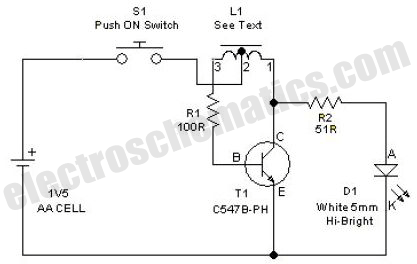
This simple LED driver circuit allows the operation of up to seven LEDs using a single NiMH (Nickel Metal Hydride) AA cell. The circuit generates voltage pulses. The LED driver circuit is designed to efficiently power multiple LEDs while maintaining...
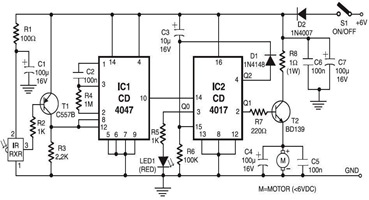
The following circuit illustrates an Infrared Toy Car Motor Controller Circuit Diagram. This circuit is based on the 4017 IC. Features: operating at .. The Infrared Toy Car Motor Controller Circuit utilizes a 4017 Decade Counter IC, which is integral...
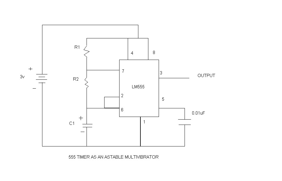
An astable multivibrator, commonly referred to as a free-running multivibrator, is a circuit that generates rectangular waves without the need for external triggering. The timing characteristics of this circuit are determined by the values of the resistors and capacitors...