
The Transistor Amplifier-P2

The described circuits utilize transistors to regulate current flow effectively, ensuring that LEDs receive a consistent current regardless of fluctuations in supply voltage. The interaction between the top and lower transistors, controlled through the resistor R, establishes a feedback mechanism that stabilizes current output. The design is particularly advantageous in LED applications, where consistent brightness is essential.
In radio applications, the dual functionality of transistors as both detectors and amplifiers enhances circuit efficiency, allowing for compact designs that can effectively process audio signals. The tuned circuit's configuration, incorporating a coil and capacitor, enables selective frequency response, which is critical for clear audio reproduction. The careful selection of capacitors based on frequency characteristics ensures optimal energy transfer between circuit stages, while the use of resistors maintains the necessary DC voltage levels. This comprehensive design approach illustrates the intricate balance between various components in electronic circuits, demonstrating their collective role in achieving desired performance outcomes.The three circuits above provide a constant current through the LED (or LEDs) when the supply rises to 15v and higher. The second and third circuits can be turned on and off via the input line. This is done by turning on the top transistor via the 2k2resistor. It keeps turning on until the voltage-drop across resistor R is 0. 65v. At this point the lower transistor starts to turn on and current flows through the collector-emitter terminals and it "robs" the top transistor of current from the 2k2 resistor. The top transistor cannot turn on any more and the current flowing though R is the same as the current flowing through the LEDs and does not increase.
The transistor is turned on via the 2k2 resistor and a voltage is developed across resistor R. When this voltage is 0. 7v, the emitter is 0. 7v above the 0v rail and the base is 1. 4v. If the transistor turns on more, the emitter will be 0. 8v above the 0v rail and this will only give 0. 6v between base and emitter. The transistor would not be turned on with this voltage-drop, so the transistor cannot be turned on any more than 0. 65v across the resistor R. Fig 71ba shows two more constant current circuits "sourcing" the LEDs. The 7 constant current circuits give you the choice of either sourcing or sinking the LED current. When the circuit turns ON, the current through R is zero and the voltage on the base of the BC547 turns it on fully.
The voltage between collector and emitter is about 0. 2v and this means the emitter of the power transistor is below the base of the BC547. The base of the power transistor is 0. 7v above the base of the BC547 and the power transistor also turns on fully. Current increases through R and when the voltage across R reaches 0. 7v, The BC547 starts to turn OFF. The collector voltage rises and this starts to turn OFF the power transistor. This is how the current through the LOAD is limited by the value of R. A transistor can be used as a "detector" in a radio circuit. The Detector stage in a radio (such as an AM receiver), is usually a crystal, but can be the base-emitter junction of a transistor. It detects the slowly rising and falling audio component of an RF signal. This signal is further amplified and delivered to a speaker. A single transistor will perform both "detection" and amplification. The first two transistors provide enormous gain and a very high input impedance for the tuned circuit made up of the 60t aerial coil and 415p tuning capacitor.
The signal generated in the "tuned circuit" is prevented from "disappearing out the left end" by the presence of the 10n capacitor as it holds the left end rigid. We have shown the coupling capacitor transfers very little energy when it does not get fully discharged during part of the cycle and this means it cannot receive a lot of energy to charge it during the "charging" part of the cycle.
This is a point that has never been discussed in any text books. It is the energy (actually the current - due to the difference in voltage between the two terminals of the capacitor) that flows into the capacitor that creates the flow of energy from one stage to the other. It is the "magnet on the door" analogy described previously. But an audio circuit has a wide range of frequencies and the lowest frequency is generally selected as the capacitor will have the highest resistance at the lowest frequency.
A 10u capacitor at 200Hz is like putting a 100R resistor between one stage and the next and a 100u capacitor at 200Hz is like putting a 10R resistor between one stage and the next. In other words, the resistor transfers approximately the same amount of energy as the capacitor but the capacitor separates the DC voltages - the capacitor allows the naturally-occurring voltages to be maintained.
In Fig 71d you can see the "resistance" of a capacitor is very small compared to the LOAD resistance (the main component that determines the amount of energy 🔗 External reference
Related Circuits
The single-junction transistor is commonly utilized in sawtooth and pulse generators, and it can also be configured to create a basic sine wave generation circuit. As an oscillator circuit composed of discrete components, it requires a minimal number of...
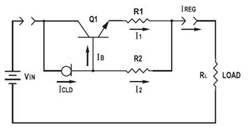
This application datasheet article includes sections that discuss the practical current booster circuit technique, which involves a conventional circuit using a Constant Current Load (CLD) and a current boosting circuit technique. It covers the analysis of the booster circuit...
This is a Mini MW (Medium Wave) Transmitter circuit. This circuit consists of a combination of transistors SA103 and SA101. These transistors are used as oscillators. The Mini MW Transmitter circuit is designed to operate in the medium wave band,...
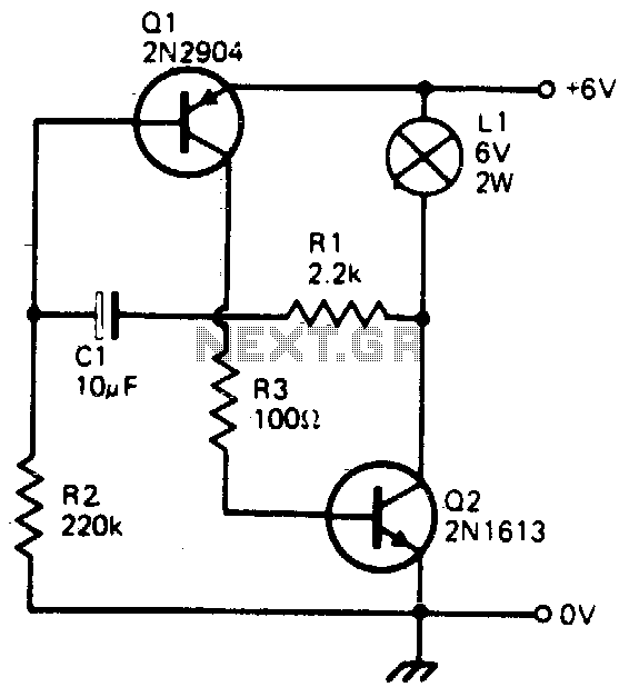
This simple circuit will flash a 6-volt lamp at a rate determined by the size of capacitor C1. It is most economical on power as it only draws current when the lamp is on. When the lamp is off,...
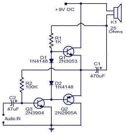
This circuit diagram illustrates a simple three-transistor audio amplifier capable of delivering approximately 100 mW of power to a 25 Ohm speaker. Diodes D1 and D2 provide a constant bias voltage for transistors Q1 and Q2. Transistor Q1 functions...
The design objective was to produce an hFE tester with switched collector currents for the DUT (Device Under Test) covering a range suitable for the selection and matching of output transistors for amplifiers such as the JLH Class-A, ESP...