
Fuse Monitor / Alarm

The described circuit provides a straightforward method for indicating the status of a fuse using minimal components. The primary components involved are a resistor and a light-emitting diode (LED).
The circuit operates by connecting the LED in parallel with the fuse. When the fuse is intact, current flows through the fuse, allowing the LED to remain off due to insufficient voltage across it. The resistor is placed in series with the LED to limit the current flowing through it, ensuring that the LED operates within its specified current rating and does not get damaged.
In the event that the fuse blows, the circuit's behavior changes. With the fuse open, the current can no longer flow through the fuse path. However, the LED will now receive voltage from the power supply directly across its terminals, causing it to illuminate. This visual indication serves as a clear and immediate alert that the fuse has blown, allowing for quick identification and replacement without needing to physically remove the fuse from its holder.
For optimal performance, the resistor value should be calculated based on the supply voltage and the forward voltage drop of the LED, ensuring that the LED receives the appropriate current for visibility. This simple yet effective design exemplifies the utility of basic electronic components in creating practical solutions for troubleshooting and maintenance in electrical systems.It came to me in a flash. A simple way to see if a fuse has blown without removing it from its holder. Its not often you can design a circuit using just two components, but with just one resistor and an LED this circuit provides visual indication of when a fuse has blown. 🔗 External reference
Related Circuits

When this alarm is activated, its siren will sound once for up to 20 minutes. After this period, it will switch off and remain off. The basic circuit features a single zone with independently adjustable exit and entry delays,...

A blocking material monitoring circuit is presented. When the optical path is obstructed by the material, the phototransistor VT1 turns off, which subsequently turns off transistors VT2, VT3, and VT4. This arrangement is coupled to a flip-flop configuration. When...

This is a simple frequency counter designed to monitor the 240VAC mains supply. It has a frequency range of 0-999Hz, allowing it to also be used with 400Hz equipment. The frequency counter circuit operates by measuring the frequency of an...
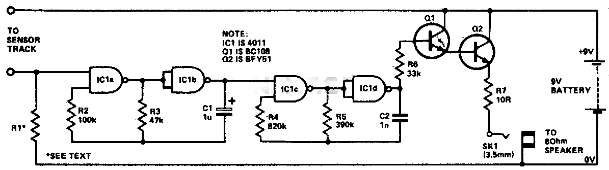
The circuit utilizes four NAND gates from a 4011 package. In each oscillator, one gate functions as a simple inverter, while the other features a control input. The oscillator's operation is disabled when this input is held low. The...

When the battery voltage is 11.5V or less, transistor Q1 is activated, and LED D1 will illuminate. When the battery voltage is between 11.5V and 13.5V, transistor Q2 is activated, causing LED D2 to light up. At a battery...

When the switch SI is open, the circuit operates as a doorbell. When SI is closed, rain falling on the sensor will activate transistor Q1, which in turn triggers Q2 and the thyristor, thereby activating the bell. Resistor R4...