
Home security monitor system

The described circuit functions as a delay timer for activating an alarm system, utilizing both normally open (NO) and normally closed (NC) contacts. The main components include three switches (SI, S2, S3) that implement the delay mechanism, allowing the alarm to be triggered after a specified period of 30 seconds. This delay feature is essential in scenarios where a temporary interruption is allowed before the alarm is activated, providing users with a grace period to cancel the alarm if necessary.
The NO contacts (SI, S2, S3) will close after the 30-second delay, completing the circuit and activating the alarm. Conversely, the NC contacts remain closed during the delay period and will open once the alarm is triggered, effectively signaling the alarm condition. The immediate action of switches S4 and S5 ensures that certain conditions can trigger the alarm without delay, providing a dual-layered response mechanism for different scenarios.
Additionally, the CANCEL switch is a critical component that allows users to reset the alarm system. When engaged, the CANCEL switch interrupts the circuit, returning the system to its initial state and preventing the alarm from sounding. This feature enhances user control over the alarm system, allowing for manual intervention without the need for waiting for the delay to expire.
Overall, the circuit design emphasizes user flexibility and responsiveness, ensuring that alarm conditions can be managed effectively while also providing an automatic delay feature for enhanced usability.This circuit provides normally open (NO) and normally closed (NC) contacts SI, S2, and S3 to turn on the alarm after a 30 second delay. S4 and S5 operate instantly The CANCEL switch resets the alarm.
Related Circuits
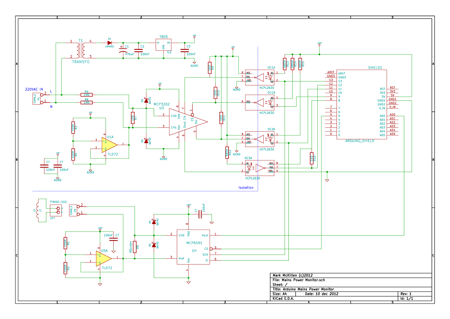
A mains (220-240VAC) power monitoring circuit has been sought for interfacing with an Arduino. While the OpenEnergyMonitor solution employs a transformer for isolation and measurement of mains voltage, it has been noted that the transformer does not couple effectively...
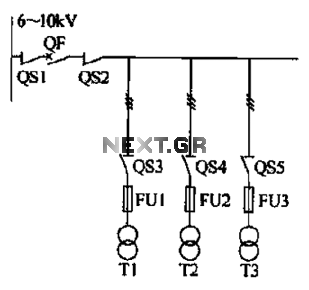
A 6-kV bus segment at the circuit breaker should be installed, but under certain circumstances, it may be equipped with an isolating switch, load switch, or isolating contact head group. These circumstances include: 1) when manual switching of the...

The hum noise is produced by an electronic device with improper design. To address this issue, it is essential to identify the source of the hum. This involves checking the grounding, cabling, casing, and other factors that may contribute...
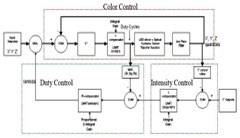
The system utilizes RGB LED light sources, an optical sensor, and a feedback controller. The purpose of employing optical feedback is to ensure color stability over temperature variations, maintain constant brightness, and control any specific color point or brightness...
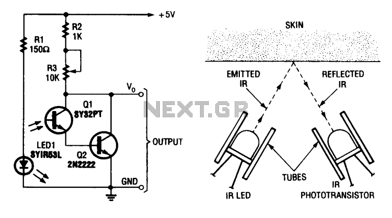
A simple heart-beat transducer can be constructed using an infrared LED and an infrared phototransistor. This system operates on the principle that skin serves as a reflective surface for infrared light. The infrared reflectivity of the skin varies depending on...
This device is designed to capture images of moving objects by activating a camera or flashgun when one or two light beams are interrupted. Originally intended for photographing insects in flight, it can also be utilized for projectiles and...