
Trip Circuit of a Circuit Breaker
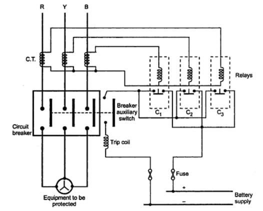
In normal operation, a separate supply is necessary for the relay's functioning. The relays are configured in a star formation, while the relay contacts are arranged in parallel. The entire relay contact unit is connected in series with the auxiliary switch, trip coil, and battery. Under normal conditions, the relay contacts remain open. When a fault occurs, the current through the relay coils surges, causing the normally open relay contacts C1, C2, and C3 to close. This action activates the trip coil of the circuit breaker. The auxiliary switch, which is mechanically linked to the circuit breaker, is initially closed. As the contacts C1, C2, and C3 close, current flows through the trip coil, energizing it and opening the circuit breaker. The mechanical linkage ensures that the auxiliary switch also opens, interrupting the current through the trip coil. This interruption isolates the faulty section and de-energizes the trip coil, returning the relay contacts to their normal position. The design of the auxiliary switch prevents arcing across the relay contacts. The make-type contact relay operates without requiring an external battery supply for tripping, as it derives the necessary energy from current transformers (CTs) or potential transformers (PTs) connected to the main supply source.
In the configuration utilizing CTs for energy derivation, the relay coil and trip coil are connected in series, with the three phases arranged in a star configuration. Under normal conditions, the relay contacts C1, C2, and C3 are closed, allowing energy for the relay coils to be sourced from the supply via the CTs. The trip coils of the circuit breaker remain de-energized during normal operation. Upon a fault, the heavy current flowing through the relay coils causes the contacts C1, C2, and C3 to open, which in turn allows current to flow through the trip coils of the circuit breaker, resulting in the circuit breaker opening. Additionally, this configuration may include an undervoltage trip coil, with all relay contacts in series with this coil, enhancing the reliability and safety of the system.Consider a simplified circuit of a typical relay as shown in the Fig. 1 usually the relay circuit is a three phase circuit and the contact circuit of relays is very much complicated. The Fig. 1 shows a single phase simplified circuit to explain the basic action of a relay. Let part A is the circuit to be protected. The current transformer C. T. is connected with its primary in series with the line to be protected. The secondary of C. T. is connected in series with the relay coil. The relay contacts are the part of a trip circuit of a circuit breaker. The trip circuit consists of a trip coil and a battery, in addition to relay contacts. The trip circuit can operate on a. c. or d. c. If the fault occurs as shown in the Fig. 1, Then current through the line connected to A increases to a very high value. The current transformer senses this current. Accordingly its secondary current increases which is nothing but the current through a relay coil. Thus the relay contacts get closed mechanically under the influence of such a high fault current. Thus the trip circuit of a circuit breaker gets closed and current starts flowing from battery, through trip coil, in a trip circuit. Thus the trip coil of a circuit breaker gets energized. This activates the circuit breaker opening mechanism, making the circuit breaker open. This isolates the faulty part from rest of the healthy system. The relay with make type contact requires auxiliary d. c. supply with its operation while the relay with break type contact uses the energy from the main supply source for its operation.
Let us see the details of these two types of schemes. As mentioned earlier, a separate supply is necessary for the relay operation. The relays are connected in star while the relay contacts are connected in parallel. The entire relay contact unit is connected in series with the auxiliary switch, trip coil and the battery. Relay contacts are open in normal position. Operation : When the fault occurs, the current through relay coils increases to a very high value. Due to this, the normally open relay contactsC1, C2and C3get closed. This activates the trip coil of a circuit breaker. The auxiliary switch is initially closed along with the circuit breaker. So when contacts C1, C2and C3are closed, the current flows through trip coil of circuit breaker. This activates the trip coil which opens the circuit breaker. As auxiliary switch is mechanically coupled with the circuit breaker, it also gets opened. This interrupts the current through trip coil. Thus supply to fault part gets interrupted and trip coil also gets de-energized. This brings the relay contacts back to normal position. Due to auxiliary switch, arcing across relay contacts gets avoided. As relay contacts are normally open and they `make` the circuit to open the circuit breaker hence called make type contact relay.
This type of relay does not require external battery supply for the tripping. The current transformers (C. T. s) or potential transformer (P. T. s) are used to derive the energy required for the relay from the main supply source. The relay using C. T. s to derive operating energy from the supply is shown in the Fig. 3. In this scheme, the relay coil and trip coil of each are connected in series. The three phases are then connected in star. Under normal working, the relay contacts C1, C2and C3are closed. The energy for relay coils is derived from supply using C. T. s. The trip coils of circuit breaker are de-energized under normal condition. When the fault occurs, heavy current flows through relay coils due to which relay contacts C1, C2and C3break. Thus current flows through trip coils of circuit breaker due to which circuit breaker gets open. In this type, in addition to normal trip coils of circuit breaker, an additional undervoltage trip coil is used.
All the relay contacts are in series with the undervoltage trip coil. Through potential transf 🔗 External reference
Related Circuits
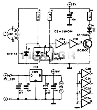
Used for digital control of musical instruments, this transmitter converts digital data signals into equivalent optical signals for a fiber optic cable interface. Optocoupler IC1 provides isolation, driving IC2-a and -b, and T1, ultimately providing a cable driver LED...
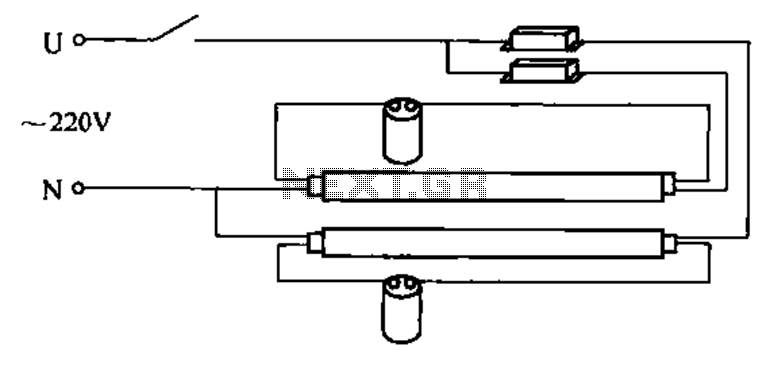
A double tube fluorescent lighting circuit is illustrated. In certain situations, a single tube light may not fulfill the lighting requirements, necessitating the use of double tube lighting. The physical installation is depicted in the circuit of a double...
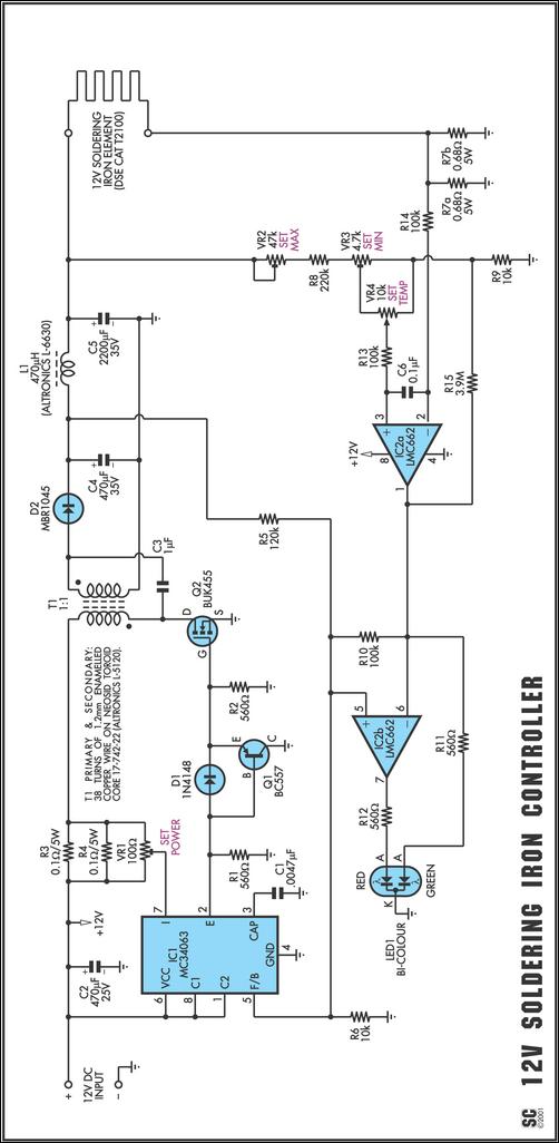
One reason commercial soldering stations are costly is that they typically require soldering irons with built-in temperature sensors, such as thermocouples. This circuit removes the necessity for a specialized sensor by detecting the temperature of a soldering iron heating...
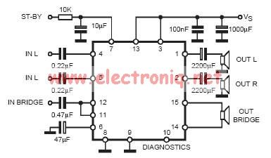
In practical applications, a series resistance must always be included. This component serves the dual purpose of limiting the current at pin 7 and smoothing the ON/OFF transitions during standby. In electronic circuits, particularly those involving integrated circuits (ICs) or...
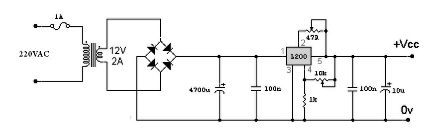
A variable power supply based on the L200 IC, where the output voltage is controlled by a 10K variable resistor. The output voltage ranges from approximately 3 to 15 volts, with a current output ranging from a minimum of...
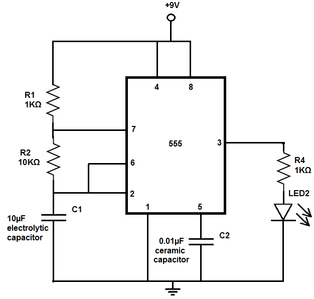
The 555 timer chip is a versatile integrated circuit (IC) that, when connected correctly, can generate pulses of current at specific intervals determined by a resistor-capacitor (RC) network. In this mode, the LED does not remain constantly lit; it...