
Mains Delay Switch For Lambs and Motors
The circuit is supplied by a relatively simple power supply with stabilization at +12V DC. With switch S1, the power supply of the circuit can be cut off if needed. LED D15 indicates that the circuit is powered, and LED D12 turns on when RL1 is activated. If not needed, it can be removed. The power of the load that RL1 will supply depends on its contacts. A relay with one or more contacts can be used.
Attention: In the entire region where high voltage exists, there is always the danger of electrocution.
The circuit described is a delay timer used primarily for controlling lamps or other appliances in various applications, such as stairwells. The design allows for multiple switches to be connected in parallel, enabling control from various locations. Each switch features an LED indicator to assist in locating it in low-light conditions, enhancing usability in dark environments.
The optocoupler IC1 serves as an isolation barrier, ensuring that any noise or unintended signals do not trigger the circuit inadvertently. The control logic is implemented using integrated circuits IC2A, IC2B, and IC2C, which manage the timing and activation of the relay. The timing for how long the lamp remains lit after the last switch is pressed is determined by the RC timing circuit formed by capacitor C2 and resistor R5, along with the variable resistor TR1, allowing for customization of the delay duration.
The relay RL1 is capable of controlling various loads depending on its contact configuration, making the circuit versatile for different applications. The entire system operates from a +12V DC power supply, and indicators D15 and D12 provide visual feedback regarding the power status and relay activation, respectively.
Safety precautions are emphasized due to the presence of high voltage in certain areas, underscoring the importance of proper insulation and handling to prevent electrocution hazards.A circuit that will find enough applications. Basically the designing became in order to exist delay in quench one or more lamps in a stairwell or in any other space exists this need. It can become use, for the control various motor or other appliances, what is connected in the contacts of J3.
The activation command is given by exterior pressing switches connected parallel [Fig2]. Does not exist restriction in the number of these switches. The switches lead with a simple cable of three cables with small diameter, to the J1. Each switch is constituted by the pressing switch and Led that works constantly, facilitating to find the place of switch in dark spaces. If the switches are placed in exterior spaces, it will be supposed they are waterproof. Parallel to the J2 terminate the switch S2, Led D9, which can be placed above in the box of circuit or near this or can be used if it does not need. If pressing anyone of switch excited the Led of optocoupler IC1 the transistor closes and grounding the entries of gate IC2A, his exit becomes High.
Capacitor C3 charges via the D2 roughly in the supply voltage. The exit of IC2B becomes Low the exit of IC2C becomes High. Transistor Q1 excites it and the RL1. His contacts close and it turns on the lamb that we have connected in his contacts, and it remains thus until discharge the C2. As soon as we stop pressing some switch the exit of IC2A goes Low, the C2 it begins discharge through the R5 and the TR1.
Proportionally the resistance of TR1 changes also the time of C2 discharge, hence also the time that the RL1 remains excited. This time depends from the prices of C2, R5 and TR1. The use optocoupler facilitates in order to we avoid problems of accidental excitation from parasitic signals in the entry of IC2A.
The circuit supplied by one relatively simple power supply with stabilization in +12V dc. With switch S1 we cut the supply of circuit if it needs. The D15 shows the circuit supplies with power and the D12 turns on when the RL1 is on. If him you do not need you can him suppress? The power of load that will supply the RL1 depends from his contacts. Can place relay with one or more contacts. Attention, in the entire region where it exists the high voltage of network, exists always the danger of electrocution. 🔗 External reference
Related Circuits
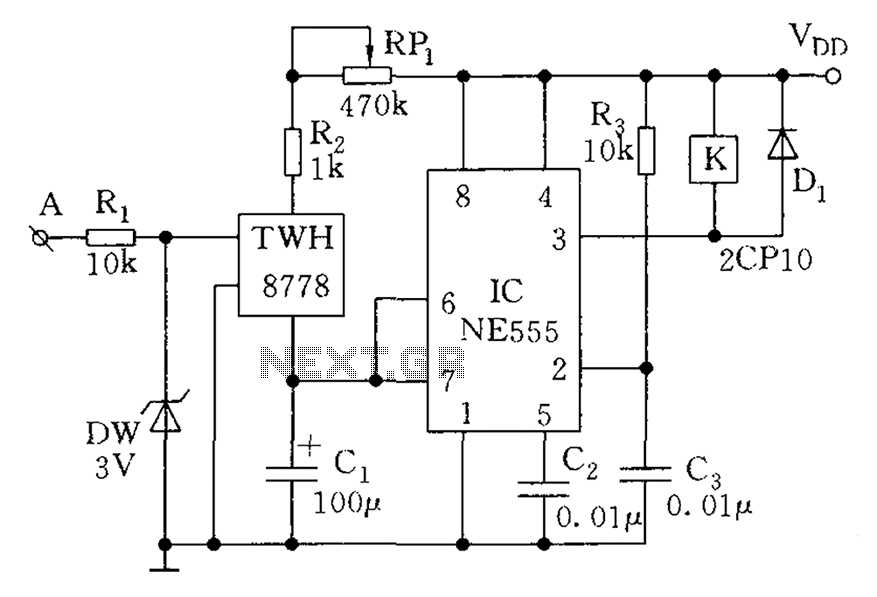
A 100 second delayed turn ON relay RL1 switch, if plug power +12V in circuit. In Fig.2 see a two range 6-60 second and 1-10 minute auto turn off relay timer circuit, with 555. Part List R1=1 Mohms C4=100nF...
Turning electrical devices ON or OFF using a remote control is a well-established concept, with numerous devices available that perform this function effectively. To create such a device, it is necessary to construct a receiver and a transmitter, as...
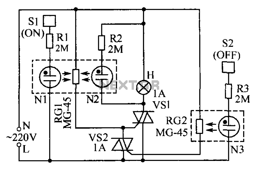
The circuit operates based on the principle that neon tubes N1, N2, and the photosensitive resistor RG1 form an optocoupler. When a finger touches the metal sheet S1, N1 lights up, causing RG1's resistance to decrease. This reduction allows...
The count switching circuit consists of an electronic switch and a pulse delay circuit for control. The count switching circuit is designed to manage the switching of signals in a controlled manner. The electronic switch serves as the primary component...
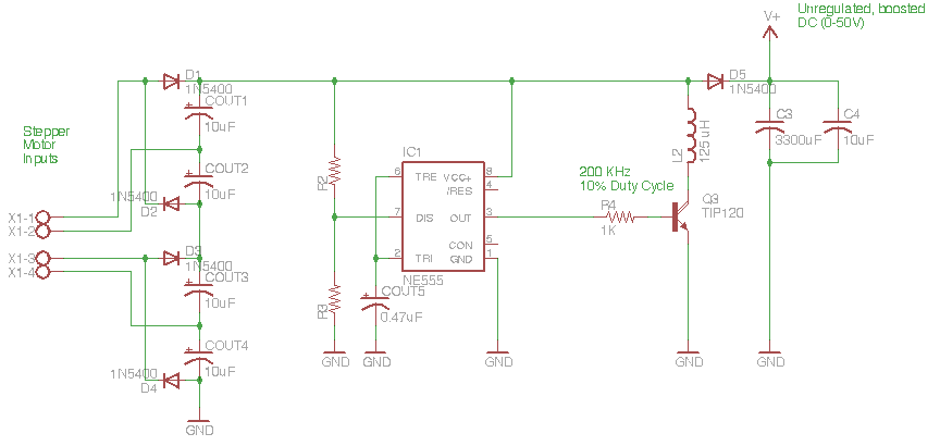
The circuit depicted in the schematic below represents an enhanced generator electronics system. It is an unregulated switcher designed to maximize sound output while ensuring prolonged CPU operation. This circuit efficiently transfers electrical energy from the generator, outperforming traditional...
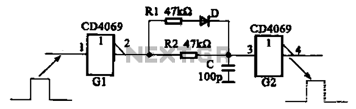
The inverter circuit using CD4069 is configured with a delay and width adjustment. When the output of the inverter (G1) is high, the capacitor (C) charges through resistor (R1) and diode (D). The voltage across capacitor C quickly reaches...