
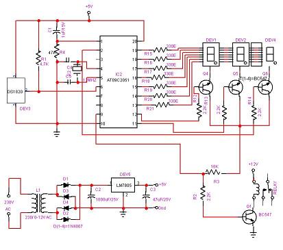
heater with ckm005 microcontroller

The control board of the induction cooker integrates a 7-segment LED display, which serves as an interface for real-time temperature and power monitoring. The presence of a fan at the base of the unit is critical for thermal management, ensuring efficient operation of the induction coil, which is constructed using Litz wire for optimal performance in high-frequency applications. The coil former's design enhances electromagnetic efficiency and minimizes losses, a crucial aspect in induction heating technology.
The power stage board is characterized by its streamlined design, which not only simplifies assembly but also enhances reliability. The inclusion of an input filter/current feeding inductor is essential for smoothing current flow and reducing electromagnetic interference (EMI). The choice of large blue capacitors for the resonant and feed tanks indicates a focus on maintaining stable operation under varying load conditions. The reduced component count compared to previous models suggests advancements in design efficiency, likely contributing to cost-effectiveness in production.
The use of a single 25N120 IGBT is particularly noteworthy, as it demonstrates the ability to achieve high power output with fewer components. This IGBT is well-suited for soft-switching applications, which are critical in induction heating for minimizing switching losses and improving overall efficiency. The design's compactness and clarity, aided by thoughtful silkscreen labeling, facilitate troubleshooting and maintenance.
The thermal management system, including the heatsink, is designed to dissipate heat generated by the bridge rectifier and IGBT, ensuring that the components operate within safe temperature limits. The use of a flyback IC and transformer for generating auxiliary voltages indicates a well-thought-out power supply architecture, crucial for stable operation of the control circuitry.
The integration of a microcontroller, likely the CKM005, reflects a shift towards more sophisticated control mechanisms within induction cookers. This microcontroller likely handles various functions such as power regulation, fault detection, and user interface management, streamlining the overall design and improving performance. The absence of traditional discrete components for sensing and control suggests a modern approach to circuit design, emphasizing reliability and efficiency.
In summary, this induction cooker exemplifies advancements in electronic design, focusing on efficiency, compactness, and ease of use while maintaining robust performance characteristics suitable for modern cooking applications.We see the control board with 7-segment LED display for temp and power readout up in front. The obligatory fan mounted down in the base of the unit, and a lovely induction coil. Looks like about the same gauge Litz wire as the Burton unit but with a much nicer coil former. We`re hoping it`s not all glued together in a big shellac clump like the Burton, so the coil can be disassembled and re-wound into a cylinder. Aside from the melted black plastic formers, it APPEARS there`s nothing too troublesome holding the coil in place, which is a very encouraging sign. Next comes the power stage board. Again, very clean and simplified design. There`s the input filter/current feeding inductor up there in the upper left, the nice hefty blue caps for the resonant tank and feed tank, and MANY fewer components than the Burton.
Compact, and probably much cheaper to produce. Ahh, the big boy himself. The venerable 25N120 IGBT. 25A and 1200V of pure power switching fury. A little slow for chopper based converters, but for this type of high current soft-switching application this device cannot be beat. It`s interesting that this cooker gets away with only a single IGBT not sure if it`s lower powered than the Burton, or whether only a single IGBT is needed to get enough power over there in 230V land.
Lucky bastards! Again, cleaner and more compact. And nicely diagrammed in white silkscreen to make circuit tracing easier! Excellent! Ad has been kind enough to label a few of the power stage components for us in red, along with their values. So that`s it for the extended tour of the insides of the new device. We`ll continue on with the remainder of the original post from yesterday as we puzzle out the function of the power stage.
But rest assured, we are now opening eBay and looking for this little gem to see for ourselves what treasures it holds. Let`s take a look and see what we can recognize. We can see the heatsink, presumably cooling the bridge rectifier and IGBTs, as well as the big fat resonant caps (light blue).
The same old 8-pin flyback IC appears near the little yellow transformer, probably making the same old 18V (or 12V) main rail for running the gate driver of the IGBT. And is that the good old 7805 linear regulator Must be the same old 5V rail for the control circuitry.
But no LM339 And no ratsnest of discrete components to do the voltage sensing, current sensing, PWM, fault protection, etc Cool! It appears to have all been replaced by a 20-pin mystery IC with the 200D-BUP label. This code is probably the model number (200W or 230V ) and revision code for the cooker. Now What`s beneath this little lady`s skirt Ad obliges to give us a peek in this next pic. CKM005ND20J. Huh 20J is probably the package code, ND may be a product option. So CKM005 is what we start googling. Not much. Guessing it`s a microcontroller gets a few sporadic hits on those junk pages listing every IC in the dictionary for sale.
So some confirmation, but not much info. Some references to EMC corporation, and other chips such as CKM002 tell us that it probably IS a microcontroller and is specifically designed for the induction cooker application. Their verbage is usually something about MCU for IH Cooker , so let`s dig even deeper. Assuming that this device is prod 🔗 External reference
Related Circuits
Best Microcontroller Projects. Do you want to learn how to use a microcontroller in your electronic projects, or do you need inspiration for your next project? If so, you have found the right place! Here is a tutorial on...
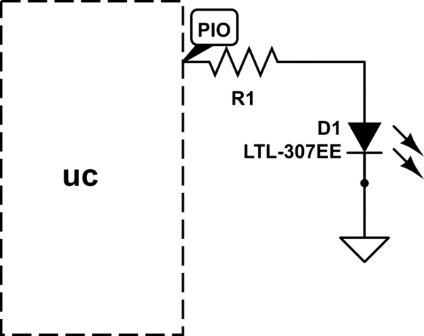
The LED will illuminate when the PIO (Programmable Input/Output) pin goes low, functioning similarly to a ground connection. In this configuration, the current is sourced from the power supply rather than the PIO, as in the first method. It...
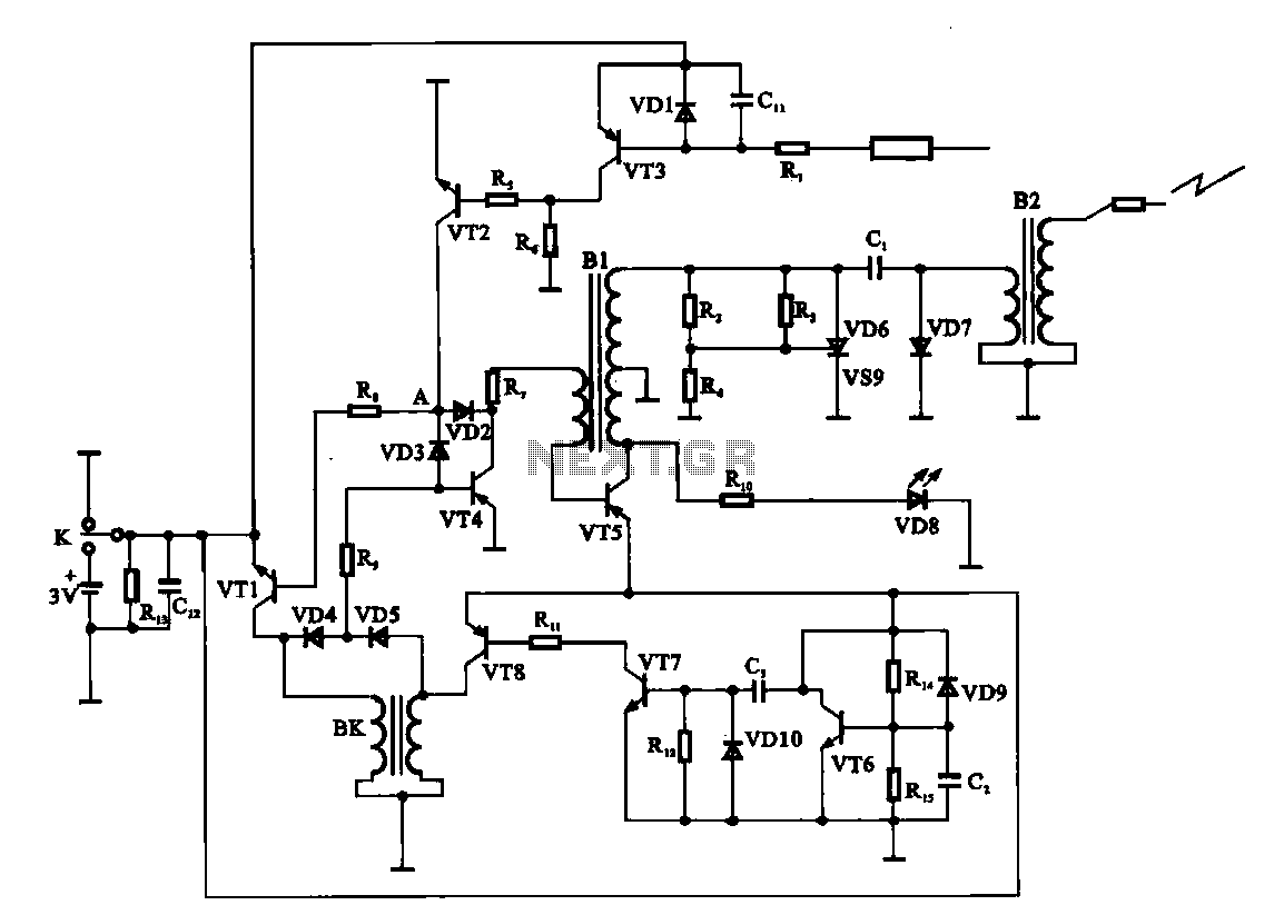
An electronic ignition circuit for a water heater is presented. When the faucet is opened, the switch activates a 3V battery. As capacitor C2 requires time to charge, transistor VT6 remains off. Meanwhile, capacitor C3 charges, allowing transistors VT7...
The filter consisting of resistors R1, R2, and capacitor C1 integrates the PWM waveform. The purpose of the operational amplifier appears to be that of a non-inverting amplifier, with the gain determined by resistors R6 and R7. However, the...
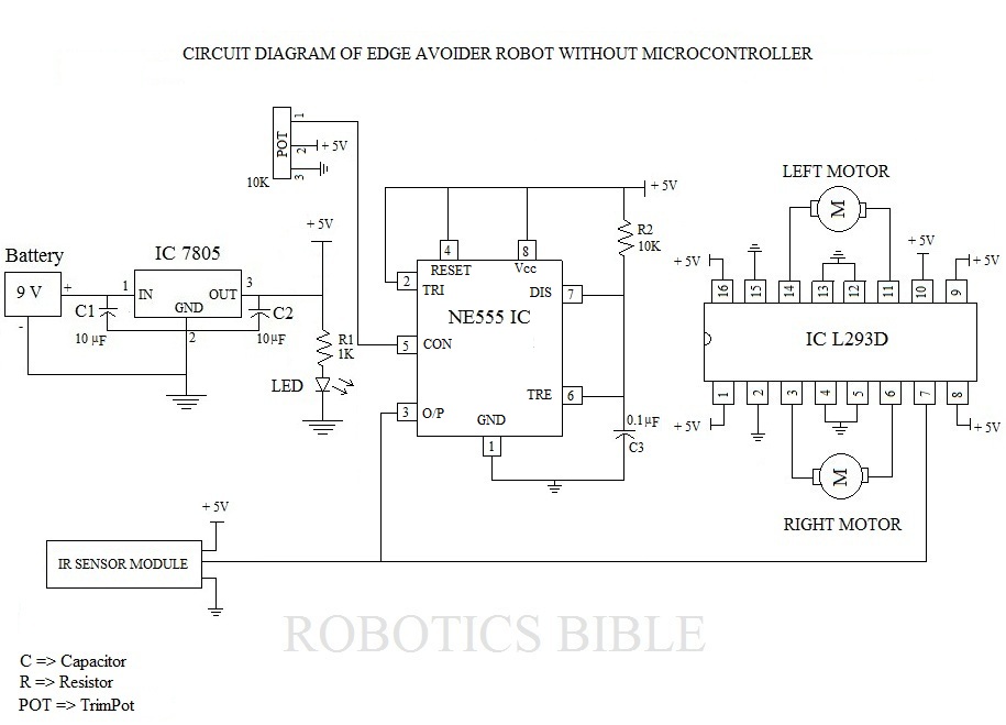
The Edge Avoider Robot (EAR) is a mobile device that detects and avoids areas where there is no surface beneath it. The Edge Avoider Robot (EAR) operates using a combination of sensors and microcontroller technology to navigate its environment effectively....
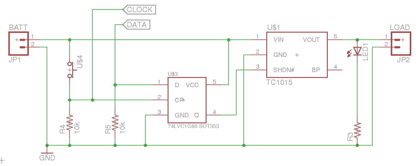
A soft power switch for a microcontroller is designed such that a momentary switch can activate the circuit, including the microcontroller. When the switch is pressed a second time, the microcontroller is capable of shutting itself down after executing...