
Protecting Microcontroller Input Pins from Soft Power Switch
The soft power switch circuit for the microcontroller is designed to facilitate an efficient power management system, ensuring that the microcontroller operates only when necessary and conserves battery life. The use of a lithium-ion battery provides a stable voltage range conducive to powering both the regulator and the microcontroller. The TC1015 voltage regulator is chosen for its low dropout voltage, making it suitable for battery-powered applications.
The implementation of a flip-flop adds robustness to the circuit. The flip-flop acts as a memory element that retains the state of the power switch, ensuring that the microcontroller can reliably detect switch presses without being affected by mechanical bounce. The initial button press activates the regulator, and the microcontroller can maintain its operation by setting the uC Power high. This design minimizes the risk of unintended resets or power cycling due to noise or bounce.
To address the potential issue of battery voltage exceeding the microcontroller's maximum I/O pin voltage, a resistor is used on the CLOCK line to limit current and protect the microcontroller. This resistor ensures that when the CLOCK line is driven high, the voltage does not exceed safe operating levels for the microcontroller.
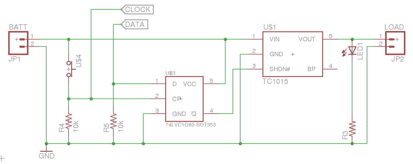
The circuit's design also considers power consumption. The use of pulldown resistors and the flip-flop configuration minimizes current draw during the off state, which is critical for extending battery life. Overall, this soft power switch circuit is a well-thought-out approach to managing power in microcontroller applications, balancing functionality with efficiency and reliability.Soft power switch for a microcontroller where a momentary switch can turn the circuit on (including microcontroller), and then when the switch is pushed a second time, the microcontroller can shut itself off after performing some clean up. I have the above circuit so far, but I`m not sure if it`ll be reliable. I`m using a lithium- ion battery (3. 7-4. 2V) and the TC1015 regulator (3. 0V output). The idea is that when the switch is pressed, the regulator turns on, then the microcontroller sets uC Power high, keeping itself on. When the switch is pressed a second time, an interrupt on uC Switch will allow the microcontroller to set uC Power low, turning itself off.
What I`m not sure about, is if I need to protect the microcontroller from battery voltage. The microcontroller I`m using has an absolute maximum voltage on the I/O pins of Vdd+0. 4V, so I`m not sure how to handle that best. Second, will this circuit actually keep the regulator from turning on when it`s in the "off" state I had thought about using a pulldown resistor on the enable line, but am worried about the current draw while the chip is powered on. The new circuit uses a flip flop, with the data line normally pulled low. Pressing the switch hits the clock, turning the system on. Subsequent presses of the switch drive the CLOCK line high (allowing the microcontroller to sense the press), but don`t affect the output of the regulator.
Once the microcontroller is ready to power off, it sets the DATA line high and then sets the CLOCK line high, which will cause the regulator to shut down. One of the really nice things about this setup, is that the first button press turns the regulator on, and keeps it on until the microcontroller is ready to shut down.
Bounce isn`t an issue, because no matter how many times the clock line goes high, the data line is still held low by the pull down. In addition, the current draw should be very minimal (just the flip flop and the TC1015 while off), and there is minimal current draw through resistors while on.
The microcontroller does need to be protected from the battery voltage on the clock line, but as @Andy aka suggested, that can be done with a resistor on CLOCK. 🔗 External reference
Related Circuits
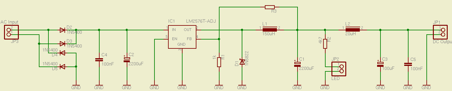
This is a simple and effective switched mode power supply (SMPS) designed to power an LCD monitor. It requires 20V at 2.3A, but the power supply unit (PSU) output voltage can be adjusted in the range of 1.2V to...
The high durability of a light-emitting diode (LED) makes it suitable for ON/OFF indicator applications. However, there are limitations regarding low operating voltage. Light-emitting diodes (LEDs) are semiconductor devices that emit light when an electric current passes through them. Their...

This circuit is a touch switch circuit, similar to a touch door alarm. It utilizes a 555 timer as the core component of the touch switch circuit. The operation begins when the plate is touched, triggering the 555 timer....
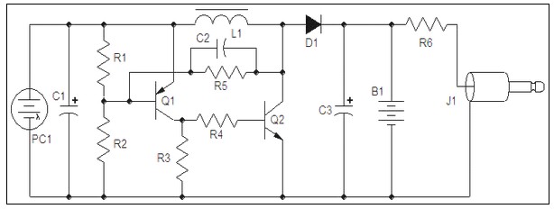
A mobile phone charger powered by a solar cell power supply is described. This system utilizes a dual comparator circuit that connects the solar panel to the battery when the voltage at the battery terminal is low and disconnects...
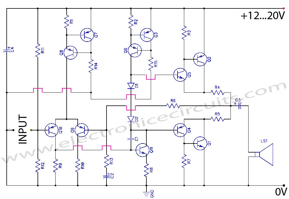
Discrete Class AB Transistor Audio Power Amplifier Circuit Diagram. This is a Class AB transistor power amplifier. It is a simple amplifier. The discrete Class AB transistor audio power amplifier is designed to provide efficient amplification of audio signals while...
This circuit is a simple form of the commercial UPS, the circuit provides a constant regulated 5 Volt output and an unregulated 12 Volt supply. In the event of electrical supply line failure the battery takes over, with no...
Warning: include(partials/cookie-banner.php): Failed to open stream: Permission denied in /var/www/html/nextgr/view-circuit.php on line 713
Warning: include(): Failed opening 'partials/cookie-banner.php' for inclusion (include_path='.:/usr/share/php') in /var/www/html/nextgr/view-circuit.php on line 713