
Water heaters electronic ignition circuit
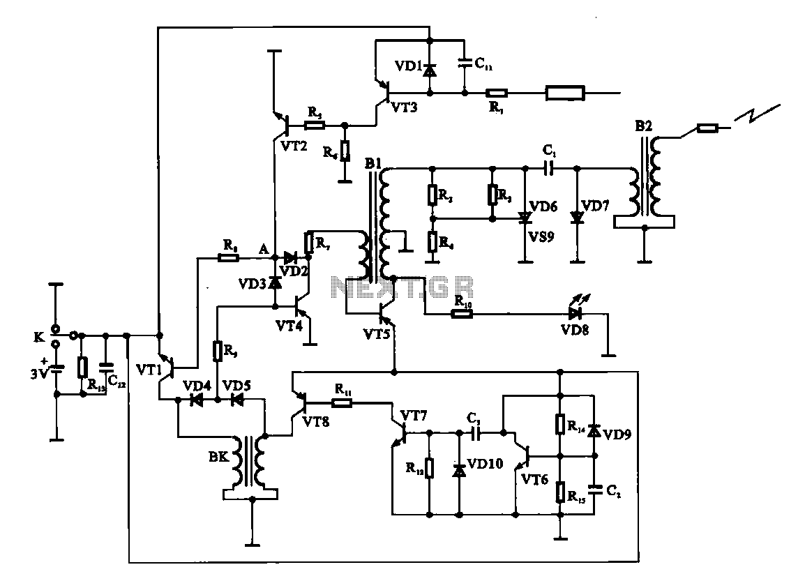
The electronic ignition circuit is designed to initiate the gas supply for a water heater in response to the demand for hot water. The operation begins when the user opens the faucet, which closes switch K, thus connecting the 3V battery to the circuit. This battery provides the necessary power for the entire ignition process.
Initially, capacitor C2 is in a charging state, which prevents transistor VT6 from turning on. This is a crucial step, as it ensures that the circuit does not inadvertently activate while the system is in an idle state. Once C2 has charged sufficiently, it allows the circuit to progress to the next stage.
Simultaneously, capacitor C3 begins to charge. The charging of C3 is vital, as it influences the operation of transistors VT7 and VT8. Once C3 reaches a certain voltage threshold, it enables VT7 and VT8 to conduct. The conduction of these transistors serves as a signal to the gas supply solenoid valve (BK), allowing it to receive power.
As a result, the solenoid valve is energized, which opens the gas valve. This action initiates the flow of gas, preparing the water heater for operation. The design of this circuit ensures that the ignition process is both efficient and safe, as it relies on the controlled charging of capacitors and the sequential activation of transistors to manage the gas supply effectively. Overall, this electronic ignition circuit exemplifies a reliable method for activating a water heater in response to user demand.Electronic ignition circuit for the water heater is shown. When you open the faucet, switch K 3V battery, since the charging C2 need room, so VT6 is off, the power supply while the C3, charging so VT7, VT8 conduction, so that the gas supply (gas) solenoid valve BK start winding is energized, the gas valve open, gas began.
Related Circuits

This linear amplifier provides a 10-W PEP output with a 1.25-W drive on the 10 m band. The transformers, T1, T2, and T3, consist of 10 turns of bifilar windings on an FT-50-43 toroidal core and are designed for...
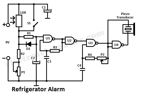
A simple light fence security beeper is presented. This circuit can function as a door alarm, gate alarm, pathway alarm, etc. It can be powered by any 12 Volt DC power supply. The operation of this circuit is straightforward....
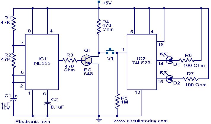
The circuit described can be utilized for tossing a coin, serving as a random generator for head or tail outcomes. This circuit is applicable in various games where a coin toss is required to initiate play. It employs two...
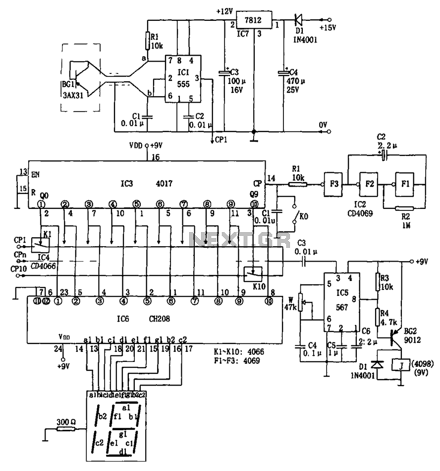
The temperature detection circuit is illustrated in Figure 10. This circuit comprises a temperature sensor, a voltage-to-frequency (V/F) converter, an oscillator, a control program for testing, an alarm system, and a decoding and display circuit. The temperature sensor used...
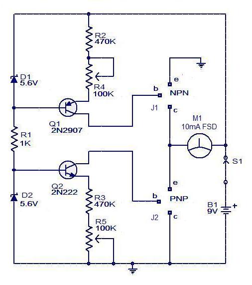
The circuit for a transistor tester is a relatively simple device. The transistor tester circuit illustrated below can be utilized to measure and identify the pins of a transistor, as well as determine its condition. Furthermore, this circuit can...
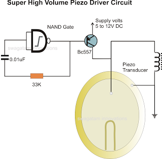
In the previous post, a piezo transducer element was discussed, along with its application in electronic circuits. This article will explore how a piezo transducer can be driven or operated using a simple circuit. The amplification method differs from...