
Thermostat controller integrated circuit schematic
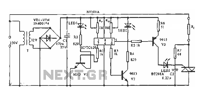
The described circuit employs a temperature sensor that continuously monitors the ambient temperature and provides feedback to the triac TC620, which acts as a switch to control power to the load based on the temperature readings. The adjustment circuit, incorporating resistors Rp1 and Rn, allows for fine-tuning of the temperature thresholds. By changing the values of these resistors, the user can set specific lower and upper limits for temperature control, ensuring that the system operates within desired parameters.
LED1 and LED2 serve as visual indicators of the temperature state. When the ambient temperature rises above the designated lower limit, LED1 lights up, signaling that the system is actively managing temperature. Conversely, LED2 provides a warning when the temperature exceeds the upper limit, indicating that the environment may be approaching an unsafe condition, prompting the need for intervention.
The choice of the triac BCR's rated current is critical and should be determined by the load's power requirements. This ensures that the triac can handle the electrical load without risk of failure. Proper selection of the triac and the associated components is essential for the reliability and efficiency of the temperature control system, making this circuit suitable for various applications where precise temperature management is necessary.As shown in Figure by the built-in temperature sensor to control the triac TC620 achieve temperature control. Adjustment circuit Rp1 and Rn can be changed each point and the lower temperature limit temperature point, LED1 lights to indicate that the ambient temperature exceeds the lower limit of temperature control point, LED2 lights to indicate that the ambient temperature exceeds the upper limit of temperature points. Triac BCR rated current selection can actually be charged according to the size of the load power.
Related Circuits
This index is organized alphabetically by each word (excluding prepositions). For instance, the "Frost Alarm" will be listed under both "A" and "F". To efficiently locate a circuit, utilize the top index or employ your browser's search feature. In...
A modulated current is supplied by the integrated rotational speed sensor KMI 15/x. This current signal needs to be converted into a ground-referenced voltage signal. The KMI 15/x sensor operates by generating a modulated current proportional to the rotational speed of...

This blog provides insights into SMPS (Switched-Mode Power Supply) circuit diagrams. It offers valuable information for those interested in understanding this topic. Switched-Mode Power Supplies (SMPS) are crucial in modern electronic devices due to their efficiency and compact design. An...

It is possible to easily generate various non-linear functions such as X^(1/2), X^2, X^3, 1/X, XY, and X/Y using logarithms. In this context, division is transformed into subtraction, while multiplication is converted into addition. The application of logarithmic properties in...
This simple alarm timer circuit is constructed using a 4060 IC, which features an integrated oscillator known for its good stability and relatively wide frequency range. The 4060 integrated circuit (IC) serves as the core component of this alarm timer...
The transmitter described here includes an additional RF power amplifier stage following the oscillator stage, which increases the output power to 200-250 milliwatts. When connected to a properly matched 50-ohm ground plane antenna or a multi-element Yagi antenna, this...