
Heating System Thermostat Circuit
The described circuit functions as a temperature control system, integrating both indoor and outdoor temperature sensors to maintain optimal heating conditions. The primary components of this circuit typically include temperature sensors, a microcontroller or comparator, relays or solid-state switches, and a power supply.
The indoor temperature sensor monitors the current temperature within the living space, while the outdoor temperature sensor assesses external conditions. The microcontroller processes the data from both sensors to determine whether to activate or deactivate the heating system. This decision is based on pre-defined temperature thresholds that can be adjusted according to user preferences or seasonal requirements.
For actuation, the circuit employs relays or solid-state switches, which are responsible for controlling the power supplied to the heating elements, such as electric heaters or a boiler. The reliability of the design is enhanced through the use of robust components and the implementation of fail-safes to prevent overheating or system failure.
Additionally, the circuit may incorporate features such as a user interface for temperature setting adjustments, LED indicators to signal system status, and communication interfaces for integration with smart home systems. Overall, this temperature control circuit is designed to ensure efficient operation and comfort in heating applications, adapting to varying environmental conditions.Controlled by indoor and outdoor temperature, Simple, high reliability design This circuit is intended to control a heating system or central heating plan.. 🔗 External reference
Related Circuits
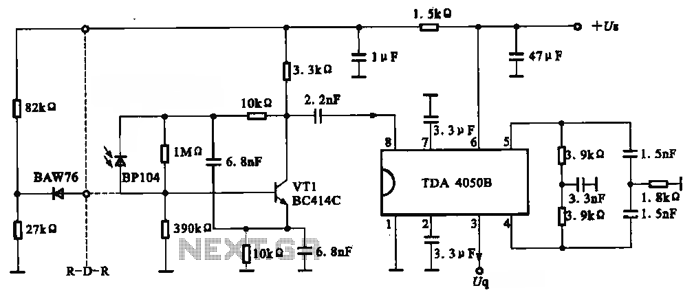
The circuit depicted is an infrared receiver circuit. It primarily consists of an infrared remote control signal switching circuit, designated as VRI, along with signal amplification, filtering, and rectifying integrated circuits, specifically the TDA4050B. The BP104 component serves as...
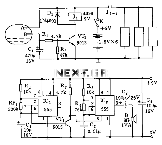
The call is triggered by the position sensing circuit, which activates the control circuit and SOS alarm circuit. This system is designed for critically ill patients or to assist disabled individuals in the event of a fall. A position...
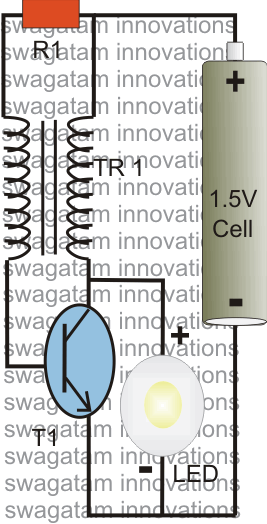
The post explains a simple 1 watt LED driver circuit using a single 1.5 V penlight cell through the joule thief concept. The coil may be wound over a T13 toroidal ferrite core using 0.2 mm or 0.3 mm...
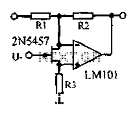
A 1.53 voltage-controlled gain amplifier (VGA) utilizes a FET connected between the two inputs of the operational amplifier (op-amp) as a voltage-controlled resistance. The resistance changes linearly with voltage and varies from several dozen square ohms, exhibiting excellent control...
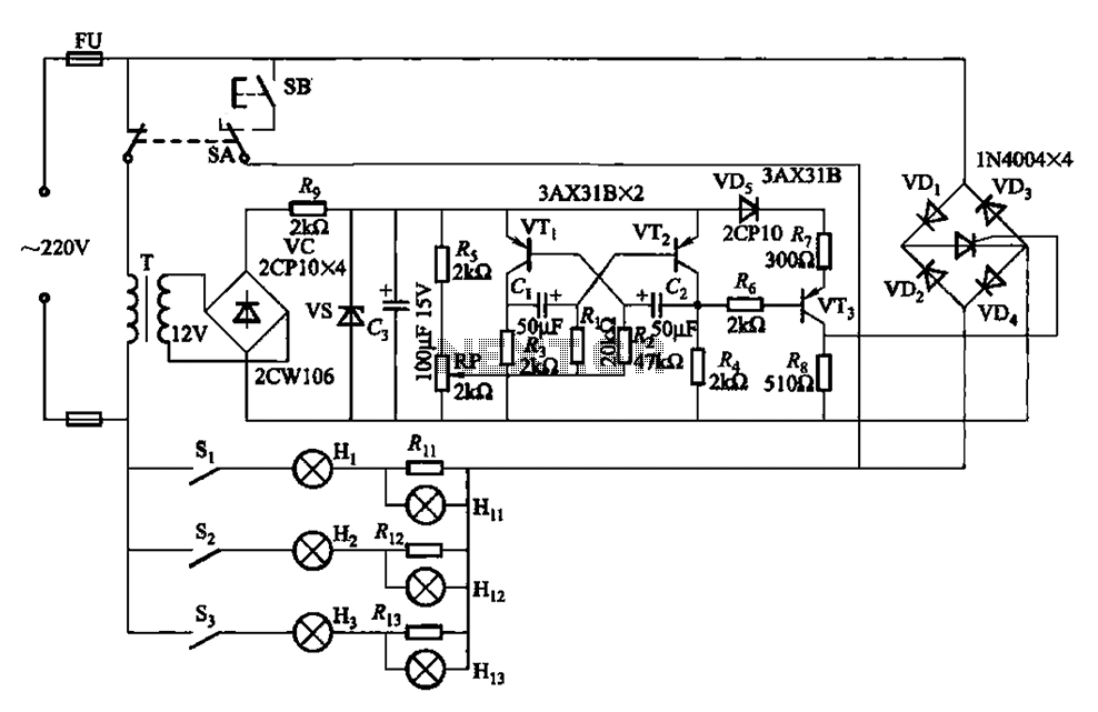
The self-excited multivibrator circuit utilizes transistors VTi and VT2 to generate an output signal that triggers a thyristor (VT3). An adjustment potentiometer (RP) is incorporated to modify the oscillation frequency, which in turn adjusts the flashing cycles of lights...
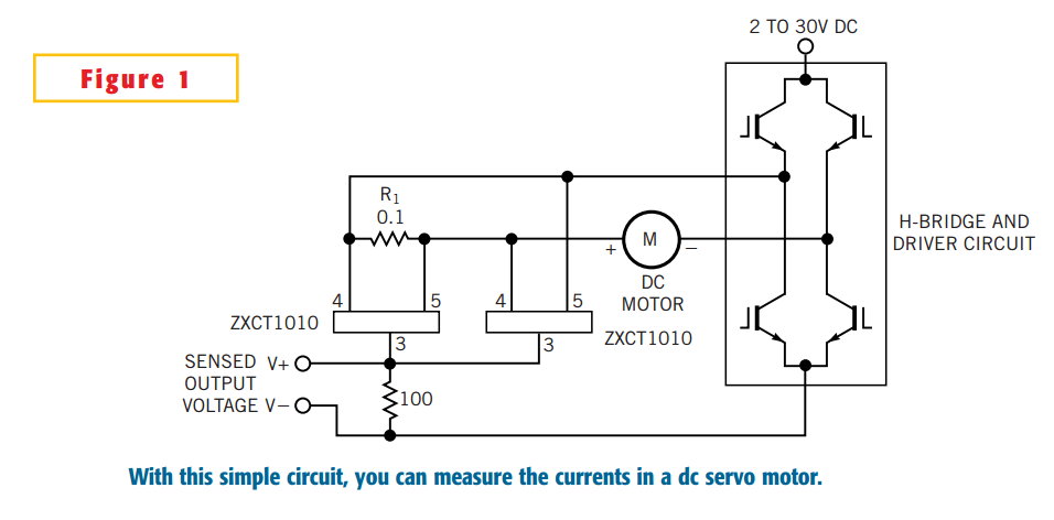
The simple circuit design in Figure 1 lets you measure all components of a current flowing in a dc servo motor. The rectified output of the circuit uses ground as a reference, so you can measure the output by...