
Ship Navigation lights circuit
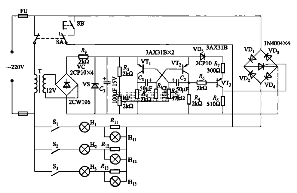
The circuit operates as a self-oscillating multivibrator, where transistors VTi and VT2 are configured to create a feedback loop that continuously switches the states of the transistors. This oscillation generates a square wave output that is used to trigger the thyristor (VT3). The thyristor, once triggered, allows current to flow through the connected load, which consists of the flashing lights.
The adjustment potentiometer (RP) plays a crucial role in determining the frequency of oscillation. By varying the resistance of RP, the time constants of the charging and discharging cycles of the capacitors in the circuit are altered, thus changing the frequency of the output signal. This adjustment directly affects the flashing rates of the lights. The Hi (red), Hz (green), and Ha (yellow) lights are connected in such a way that their flashing cycles correspond to the frequency set by the potentiometer.
The design allows for visual feedback through the colored lights, providing a clear indication of the operational state of the circuit. The use of different colors for the lights also facilitates easy identification of the flashing patterns, making it user-friendly for applications that require visual signaling. Overall, this multivibrator circuit is a practical implementation for creating variable flashing light signals using simple electronic components. By the transistor VTi, VT2 composition self-excited multivibrator output signal VT3 put large after a thyristor trigger pulse. Adjustment potentiometer RP, can change the oscil lation frequency, thereby adjusting the flashing lights Hi (red), Hz (green), Ha (yellow) flash cycle.
Related Circuits

A simple frequency meter or frequency counter circuit featuring an LCD display and an AVR microcontroller. This includes a DIY schematic circuit diagram and embedded C code. The frequency meter circuit is designed to measure the frequency of input signals...

Figure 4-27 (b) line demonstrates a configuration that enhances the output current waveform DC voltage compared to the line in Figure 4-27 (a). This configuration can be utilized for motors with larger capacities. The circuit illustrated in Figure 4-27 (b)...
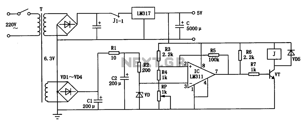
The circuit depicted can be utilized to operate at a voltage of +5V for Single Board Computer (SBC) power, preventing damage caused by over-voltage from the power supply throughout the SBC. This circuit serves as a protective mechanism for Single...
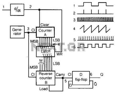
An input rectangular signal is differentiated to produce short impulses from its edges. These impulses transfer the content of counter A to a latch that clears the counter after a very brief period. Counter A counts impulses at a...

A simple circuit that can generate an inverted square wave similar to the one used by the inventor on his function generator. To construct a circuit that produces an inverted square wave, a basic approach involves using a 555 timer...
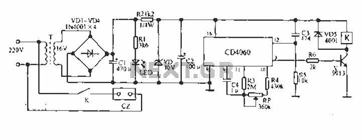
A CD4060 production time controller circuit is illustrated below. It is connected in such a way that R5 and C3 form a differential circuit to create a delay time from the start. Under the influence of the oscillating signal,...
Warning: include(partials/cookie-banner.php): Failed to open stream: Permission denied in /var/www/html/nextgr/view-circuit.php on line 713
Warning: include(): Failed opening 'partials/cookie-banner.php' for inclusion (include_path='.:/usr/share/php') in /var/www/html/nextgr/view-circuit.php on line 713