
Help in identifying the schematic symbol
The circuit design incorporates various stages, including a modulator and an amplifier, which necessitates careful physical separation to minimize interference and maintain performance integrity. The use of a metal plate as a physical barrier between the modulator and amplifier stages is critical, as it serves to shield the components from electromagnetic interference (EMI) and helps establish a common ground reference for the circuit. The plate must be securely soldered to the enclosure, ensuring that it is electrically connected to the ground plane, which is essential for reducing noise and enhancing signal stability.
Feeding signals through a hole in the metal plate requires the implementation of appropriate insulation methods. The use of a ceramic tube or insulating material is vital to prevent unintended grounding or short circuits, which could compromise circuit functionality. The implementation of feedthrough components allows for a more organized approach to signal routing and helps maintain the integrity of the DC and RF signals within the circuit.
The housing of the circuit in a metal box not only provides structural support but also acts as an effective shield against external RF interference, which is particularly important in communication applications. The design should ensure that all components are securely mounted and that any connections are robust to prevent signal degradation.
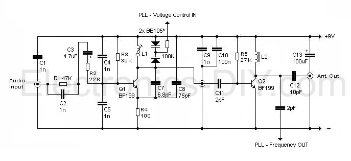
In summary, the circuit design necessitates careful consideration of component placement, grounding techniques, and shielding methods to achieve optimal performance. Each element, from the modulator to the amplifier and the use of feedthrough components, plays a crucial role in the overall functionality of the circuit, making it essential to adhere to best practices in electronic design and assembly.This circuit seems interesting and I wanted to simulate and construct it, but the problem is I do not know what do the 3 symbols in the circuit represent (1 in audio input, 1 in the middle, and 1 at the antenna). I have never come across with these symbols before. It`s not, IMO it`s showing that another `connector` or take off could be installed at that point for some reason.
If you do not require that take off, just consider it a non-connection like this. And also, in constructing the circuit physically, 1st stage (modulator) and 2nd stage (amplifier) should be seperated from each other by a metal plate right, but physically connected by a wire without using co-axial cable as shown in the figure above The circuit is probably meant to be constructed in a metal (steel) box or rectangular tube. The metal is the circuit ground. You place a steel sheet with a hole in it between the two sections of the circuit, and solder it to the metal on three sides (the fourth side is formed by the clip-on steel cover), and feed the signal through the hole, using insulation, or a ceramic tube, to insulate the wire so it can`t make contact with the plate.
You can also get complete feedthrough components that you solder to the hole, which have a connection on each side. Open up a TV tuner or modulator; you may see something similar. The circuit is probably meant to be constructed in a metal (steel) box or rectangular tube. The metal is the circuit ground. You place a steel sheet with a hole in it between the two sections of the circuit, and solder it to the metal on three sides (the fourth side is formed by the clip-on steel cover), and feed the signal through the hole, using insulation, or a ceramic tube, to insulate the wire so it can`t make contact with the plate.
And also, in constructing the circuit physically, 1st stage (modulator) and 2nd stage (amplifier) should be seperated from each other by a metal plate right, but physically connected by a wire without using co-axial cable as shown in the figure above In the image above there is a feedthrough cap on the right hand side metal wall bringing DC into that section. The feedthroough cap stops RF leaveing via the DC feedline 🔗 External reference
Related Circuits
The primary issue with the design of a stereo amplifier that includes a total bass driver is that the signals from the left and right channels eventually become combined. This summation process minimizes the separation between channels, compromising the...
This USB circuit utilizes an integrated circuit (IC) to convert digital voice data into an analog format, making it suitable for headphone use. Additionally, the output can be amplified through a power amplifier, allowing the sound to be played...
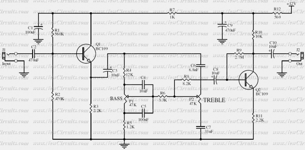
Based on the classic Baxendall tone control circuit, this provides a maximum cut and boost of around 10dB at 10KHz and 50Hz. As the controls are passive, the first transistor, Q1, is configured as common-collector to act as a...
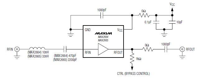
A simple, low-cost, and ultra-compact VHF/UHF low-noise amplifier circuit can be designed using the MAX2664 and MAX2665 ultra-compact LNAs for VHF/UHF applications. These devices incorporate a broadband LNA with an integrated bypass switch. The MAX2664 covers the UHF frequency...
AC power is rectified and applied to the motor in one polarity when the momentary switch is held in one direction, and the polarity is reversed when the motor is held in the reverse direction. The remote car starter...
This device functions as a simple timer that keeps the vehicle's headlights on for approximately 1 minute and 30 seconds, allowing access to dark areas without the need to return and switch off the lights. Pressing switch P1 enables...