
Led or Lamp Flasher Circuit

The circuit is intended to facilitate the operation of existing DC lamps that are integrated into a circuit. It is optimized for a voltage range of 3 to 24 volts, making it suitable for various applications where different lamp voltages may be encountered. The design ensures that these lamps can maintain a steady illumination level, which is crucial for applications requiring consistent lighting.
The schematic typically includes a power supply section capable of converting the input voltage to the required levels, ensuring that the lamps receive a stable and appropriate voltage. A control mechanism, such as a transistor or relay, may be employed to manage the on/off states of the lamps, allowing for efficient operation without flickering or power surges that could damage the lamps.
Additional components may include resistors to limit current flow, capacitors for smoothing out voltage fluctuations, and diodes to prevent back EMF when inductive loads are involved. The circuit layout should be designed to minimize interference and ensure reliability, with careful attention to the thermal management of components to prevent overheating.
In summary, this circuit serves as a reliable solution for maintaining continuous operation of DC lamps within the specified voltage range, ensuring effective lighting in various applications.Ideal to operate 3 to 24V DC existing on-circuit lamps This circuit was designed to provide that continuous light lamps already wired into a circuit, beco.. 🔗 External reference
Related Circuits
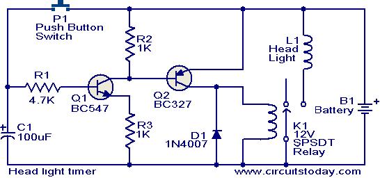
This circuit is a compact timer that keeps the headlights of a car on for approximately 1.5 minutes before turning them off. Incorporating this circuit into a vehicle allows access to dark areas without the need to return and...
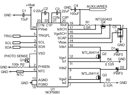
This white LED driver circuit project utilizes the NCP5680 high-efficiency white LED driver integrated circuit (IC). The NCP5680 supports dual power flash LED and torch operations. Its built-in DC/DC converter employs a highly efficient charge pump structure with operating...
The core multi-resonant circuit 40 L06 has a collapse time of 1C. An auxiliary electric signal operates below its low threshold, opening Icl. The output is provided through two terminals for business use. The circuit includes components such as...
Here a simple design for an attractive tone. They operate on a passive principle, ie without amplification. The circuit only weakened and therefore require no power. As can be seen, the circuit is built with two T-filters in the...
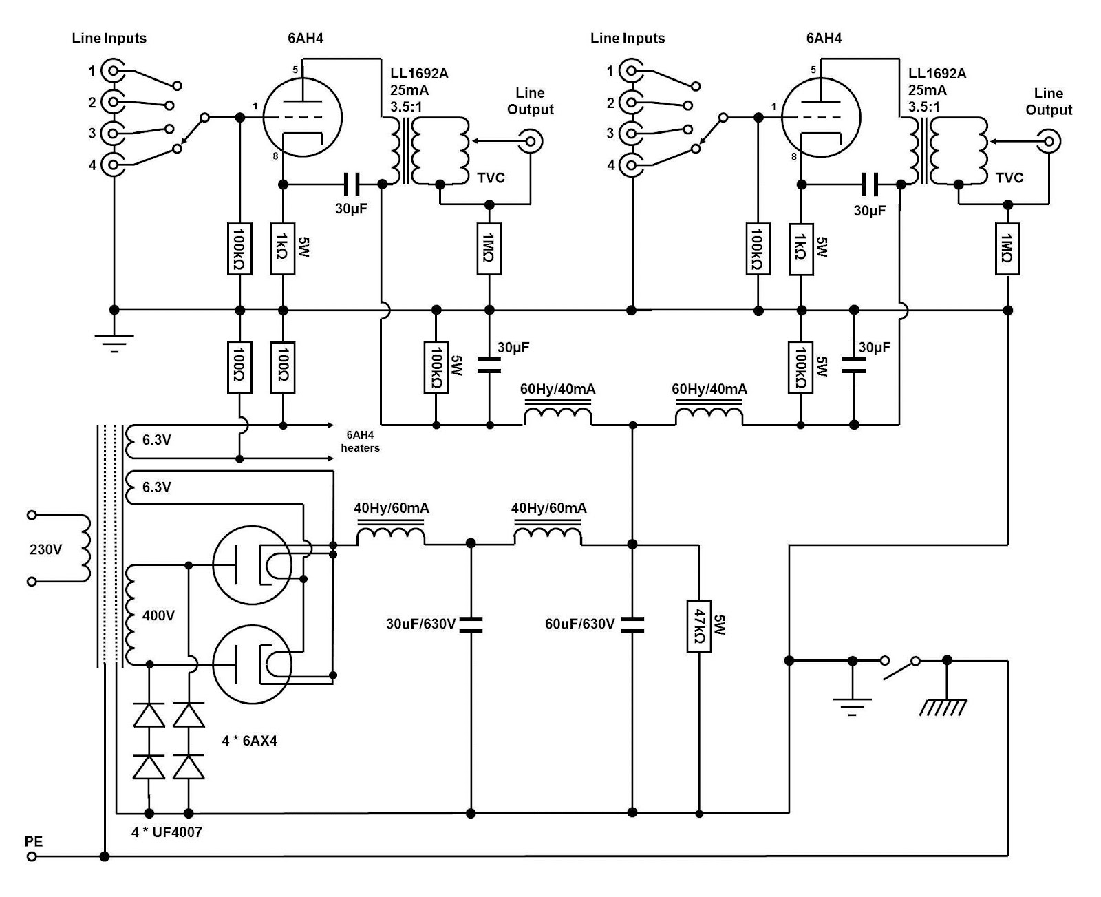
The circuit and assembly process of the line stage is presented in two separate articles. This linestage shares the same circuit as the two chassis version previously described. However, in this design, the power supply and preamplifier are housed...
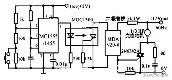
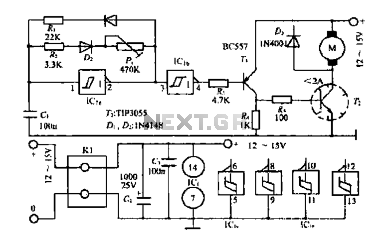
The switch shut-off time delay circuit consists of a timer, optocouplers, a bridge SCR, and an SCR AC switch. When the control button is released, it allows the motor or other AC power to remain active for one hour....