
tesla circuit

The described apparatus is fundamentally a high-voltage transformer system designed for generating and manipulating electrical energy at high frequencies. The primary and secondary coils are engineered to resonate at specific frequencies, allowing for efficient energy transfer. The construction materials, such as rubber for insulation and mica for the spark gap, are chosen for their electrical properties, ensuring safety and performance. The use of oil in the capacitors serves to enhance dielectric strength, thereby supporting higher voltage operations while reducing the risk of electrical breakdown. The overall design reflects advanced principles of electromagnetic theory, particularly in the context of resonant circuits, where the interplay between inductance and capacitance is exploited to achieve voltage amplification. This setup not only demonstrates Tesla's innovative approach to electrical engineering but also serves as a foundational concept for modern high-voltage applications in various fields, including telecommunications and power transmission.The American Electrician gives a description of one wherein a glass battery jar, six inches by eight inches, is wound with 60 to 80 turns of American wire gauge No. 18 B & S magnet wire. Into this is slipped a primary consisting of eight to ten turns of AWG No. 6 B & S wire, and the whole combination immersed in a vessel containing linseed or mine ral oil. (Norrie, pg. 34-35) Following the initial research of voltage and frequency by William Crookes, Tesla developed a series of coils that produced high-voltage, high-frequency currents. In the majority of Tesla`s experiments, he used machinery of his own design to produce the Tesla effect.
These early coils would use the "disruptive" action of a spark gap in their operation. The setup can be duplicated by a Ruhmkorff coil, two condensers (now called capacitors), and a second, specially constructed, disruptive coil. (Norrie, pg. 228) The Ruhmkorff coil, being fed from a main source, is wired to capacitors on both ends in series.
A spark gap is placed in parallel to the Ruhmkorff coil before the capacitors. The discharge tips were usually metal balls under one inch in diameter, though Tesla used various forms of dischargers. The capacitors were of a special design, small with high insulation. These capacitors consisted of plates in oil that were movable. The smaller the plates, the more frequent the discharge of this early coil apparatus. The plates also help nullify the high self inductance of the secondary coil by adding capacity to it.
Mica plates were placed in the spark gap to establish an air current jet to go up through the gap. This helped to extinguish the arc, making the discharge more abrupt. An air blast was also used for this objective. (Norrie, pg. 230-231) The capacitors are connected to a double primary (each coil in series with a capacitor). These are part of the second specially constructed disruptive coil. The primaries each have twenty turns of No. 16 B & S rubber covered wire and are wound separately on rubber tubes not less than a 1/8th inch thick. The secondary has 300 turns of No. 30 B & S silk-covered magnet wire, wound on rubber tube or rod, and the ends encased in glass or rubber tubes.
The primaries must be large enough to be loose when the secondary coil is place between the coils. The primaries must cover around two inches of the secondary. A hard rubber division must be placed between these primary coils. The ends of the primaries not connected with the capacitors are lead to a spark gap. (Norrie, pg. 35-36) Tesla`s later coils were considerably larger and operated at much higher power levels. These later systems were powered from large high voltage power transformers, used banks of glass bottle capacitors immersed in oil to reduce corona losses, and used rotating spark gaps to handle the higher power levels. Tesla also dispensed with using oil to insulate the transformer coils, relying instead on the insulating properties of air.
Tesla coils achieve great gain in voltage by loosely coupling two resonant LC circuits together, using an air-core (ironless) transformer. Unlike a conventional transformer, whose gain is limited to the ratio of the numbers of turns in the windings, Tesla coils` voltage gain is proportional to the square root of the ratio of secondary and primary inductances.
When Tesla patented a later device (U. S. Patent 1, 119, 732 ” Apparatus for Transmitting Electrical Energy), he called it a high-voltage, air-core, self-regenerative resonant transformer that generates very high voltages at high frequency. However, this phrase is no longer in conventional use. This later coil type is the usual device built by modern enthusiasts. It is an air-core, dual-tuned resonant transformer that generates very high voltages at radio frequencies (RF).
The coil achieves a great gain in voltage by transferring energy from one resonant circuit (the primary) to the other (the secondary) o 🔗 External reference
Related Circuits
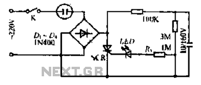
20V child-friendly power supply circuit for a foreign vine wine light, including a bulb and plug. The circuit features a bridge rectifier. The lamp access point is designed for a 10-100W bulb with a compact size. The output is...
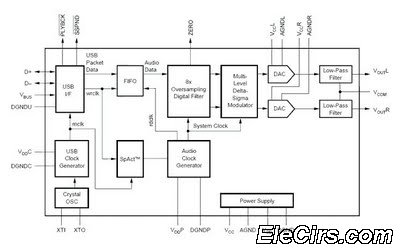
The USB sound card circuit utilizes the PCM2702 integrated circuit (IC) to create a fully functional USB sound card. The design is straightforward, allowing for the easy implementation of audio processing capabilities. The PCM2702 is a versatile USB audio controller...
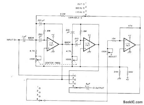
The circuit utilizing Optical Electronics 9803 operational amplifiers separates an audio frequency (AF) input signal into two outputs. The low-pass output allows frequencies from DC up to 10 Hz, while the high-pass output encompasses frequency content above 10 Hz,...
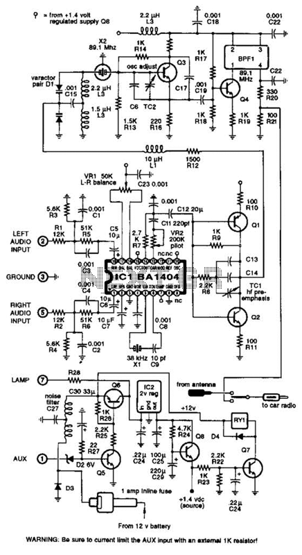
A BA1404 integrated circuit (IC) is utilized to generate a complete FM multiplex (MPX) signal. The chip incorporates all necessary circuitry. Components CI, R3, R4, and C4 are responsible for providing pre-emphasis. The transmitter operates on a single AA...
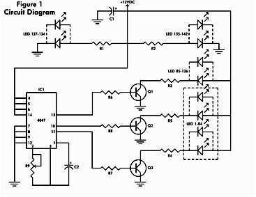
It consists of a 4047 low-power monostable/astable multivibrator, IC1, used in the astable mode to provide the timing pulses to control the flash rate of the LEDs. To accomplish the astable mode, pins 4, 5, 6, and 14 are...
Every inexpensive energy-saving lamp contains a self-resonant voltage inverter designed for low-power operation, typically up to a few watts. It raises the question of why not scale up this concept and replace the resonance circuit used to generate the...