
Improved Cmos Multivibrator Circuit

The circuit utilizes a voltage divider configuration formed by resistors R1 and R2. The primary function of this voltage divider is to scale down the input voltage supplied to the operational amplifier or multivibrator IC (IC1-a). By carefully selecting the values of R1 and R2, the designer can ensure that the voltage at the input of IC1-a remains within safe operating limits, preventing the protective diodes from conducting. This is crucial, as diode conduction could lead to undesirable circuit behavior or damage.
The inclusion of resistor R2 serves a dual purpose. Not only does it provide protection by limiting the input voltage, but it also plays a role in the feedback mechanism of the circuit. The feedback resistor R1 works in conjunction with R2 to set the gain of the multivibrator, thereby influencing its oscillation frequency and stability characteristics.
In terms of thermal performance, the circuit's design mitigates the effects of temperature variations on the operational parameters of IC1-a. By maintaining a stable input voltage, the multivibrator can operate consistently across a range of temperatures, which is essential for applications requiring reliable performance.
Overall, the combination of R1 and R2 as a voltage divider enhances the robustness of the multivibrator circuit, ensuring that it functions effectively while safeguarding against potential voltage spikes or thermal fluctuations. This careful design consideration is vital for applications where precision and reliability are paramount. This circuit uses a protective resistor R2 in conjunction with feedback resistor Rl. Together, they form a voltage divider to reduce the input voltage amplitude for ICl-a so that the protective diodes never conduct. This improves temperature and voltage stability of the multivibrator.
Related Circuits
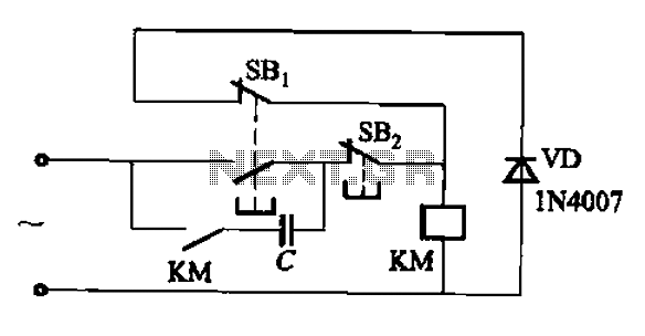
An AC contactor switch, when used with DC or pulse DC excitation, can minimize short circuit and core power consumption. This results in a significant reduction in the power consumption of the electromagnet, which can eliminate noise and reduce...

This is a design circuit diagram of a versatile FM transmitter. This circuit does not include a coil and is simple and easy to assemble. It operates based on gate logic concepts. The circuit features a buffer gate N1...
Ambient light is increasingly being utilized as an energy source. To assist designers in developing such systems, this circuit effectively measures ambient light intensity across four decades of measurement. The design is cost-effective, and with the sensor housed in...
An LED is usually a series resistor needed to ensure that the LED does not get too much power. The disadvantage of such resistance is that the current through the LED and thus the brightness changes as the voltage...
Delay electronic doorbell circuit - touch doorbell amplifier circuit The delay electronic doorbell circuit is designed to provide a user-friendly interface for doorbell activation, utilizing a touch-sensitive amplifier circuit. This circuit typically incorporates a touch sensor that detects user interaction,...
This microphone preamplifier utilizes the low-noise integrated circuit (IC) uA739. The circuit serves as an example of an effective design for preamplifying dynamic microphones. The IC contains two operational amplifiers. The uA739 is a precision integrated circuit known for its...