
HF to LF Converter
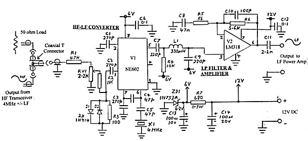
The described circuit serves as a versatile converter allowing various modulation modes from HF to LF, facilitating effective communication in amateur radio applications. The use of the NE602 mixer enables efficient frequency conversion, while the inclusion of protection diodes ensures circuit integrity against excessive RF levels. The adjustable attenuation network allows for fine-tuning of the input signal, ensuring optimal performance and minimal distortion. The design's adaptability to different crystal frequencies provides flexibility in operation, accommodating various HF transceivers.
The power supply design incorporates a dual-voltage system, ensuring that the NE602 operates effectively while maintaining the necessary bias for the output amplifier. This arrangement not only simplifies the overall circuit design but also enhances reliability during operation. The gain adjustment through resistor and capacitor modifications allows for customization based on specific requirements, making the circuit suitable for a range of applications in the amateur radio domain. The inclusion of low-pass filtering further ensures that unwanted mixing products are effectively suppressed, maintaining signal clarity and fidelity in the LF output. Overall, this circuit design exemplifies a well-engineered solution for HF to LF conversion, facilitating enhanced communication capabilities for amateur radio enthusiasts.Any mode (e. g. CW, AM, SSB, FSK) which is initiated in the HF transmitter or transceiver can be regenerated at LF (100 to 200 kHz) using this simple converter. The output at LF can be used to drive an LF Power Amplifier. The February, 2000 issue of Amateur Radio (ref. 1) contained an article I had submitted on an LF transmitter. The transmitter wa s designed for CW operation but the power amplifier was operated in a linear mode and it was only a matter of replacing the VFO with some form of AM or sideband generator with an LF output to operate on speech. The article was followed up with a further article (Amateur Radio September 2000, ref 2) on a Single Sideband Generator using the phasing technique.
The design aimed at making a stand-alone unit because of the possibility of using the unit at a site away from the amateur station. However it was pointed out that a simpler arrangement might be achieved at the amateur station site by heterodyning down from the HF output of the local HF transceiver.
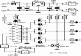
This third article describes a circuit designed to do that conversion and provide sufficient LF output level to drive the original power amplifier. The circuit diagram of the converter is shown in figure 1. The conversion takes place in V1 (type NE602). The V1 circuit is almost identical to that used in my Active Loop Converter (Amateur Radio July, 2000 - ref 3) except that the input and output frequencies are reversed.
I used the same 4 MHz xtal as in the receive converter as I had another one spare. Most HF amateur transceivers tune up to 4 MHz on the 3. 5 MHz band so that it is simply a matter of setting the transceiver frequency to 4 MHz minus the LF transmission frequency. (4 MHz plus LF transmission frequency could also be used if the transceiver is tuneable above the 4 MHz.
- This would make easier setting of the required HF frequency. Of course there is nothing to prevent some other crystal frequency being used with appropriate setting of the transceiver output frequency. ). The overall circuit gain of V1 and V2 is arranged so that the HF input to V1 operates around 20 to 30 mVPP for peak signal level.
This was chosen as it was anticipated that above these levels, steep increase in the level of intermodulation products could cause distortion in the audio signal when demodulated. This effect, relevant to the NE602, was discussed in one of my previous articles ( A. R. Jan 1994, ref 4). There is no point in running the HF transmitter at high output level to generate a signal. I reduced the power on an FT101B used to around 1 watt by backing off drive to the PA. The output is loaded into a dummy load and paralleled off to an attenuation network R1-RV1-R2-R3. (Note the connection via the coaxial T connector in figure 1. ). The precise amount of drive for a given HF transmitter power is set by RV1. Diodes D1 and D2 provide some protection to V1 in the event of excessive RF level. To attenuate mixing products above 200 kHz, the LF output from converter V1 is fed into a low pass network formed by L1-C9 and the feedback circuit of V2.
The following LF Power Amplifier requires 6VPP at maximum swing and stage V2 raises the output from V1 to this level. The circuit is similar to that used at the output of SSB modulator (ref 2) but the gain has been raised from the original value of 10 to around 70 by changing the values of R5 and C8 to those shown.
With this arrangement, the 6VPP is achieved with around 25mV of HF signal at V1 input. Maximum possible output level from V2 is 9VPP. The complete converter is powered from 12V DC and when operated in conjunction with the Power Amplifier (ref 1), the supply it is picked up from 12V in the Amplifier unit. A further 6V rail is derived with Zener diode ZR1 and resistor R7. This is used to power the NE602 converter, V1 and to set the operating point of amplifier V2 at half its12V operating supply.
Load current at 12 volts is 15mA. There 🔗 External reference
Related Circuits
The demand for high-quality electric energy in modern industrial development is increasing, making it essential to provide safe and reliable green power to energy consumers. Uninterruptible Power Supplies (UPS) are crucial for improving electric energy quality and ensuring the...
A low-cost converter is capable of supplying constant AC currents up to 1 A over variable loads. The low-cost converter is designed to provide a stable output of alternating current (AC) while accommodating fluctuating load conditions. This capability is essential...
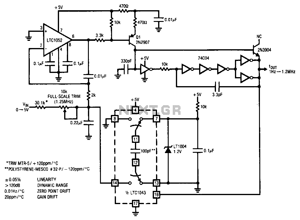
This stabilized voltage-to-frequency converter operates within a range of 1 Hz to 1.25 MHz, featuring a linearity of 0.05% and a typical temperature coefficient of 20 ppm/°C. The circuit is powered by a single 5-V supply. It employs a...
There are monitors that feature only three BNC inputs and utilize composite synchronization (sync on green). This circuit has been specifically designed for such monitors. The design maintains simplicity while delivering reasonable performance. The operational principle is straightforward. The...
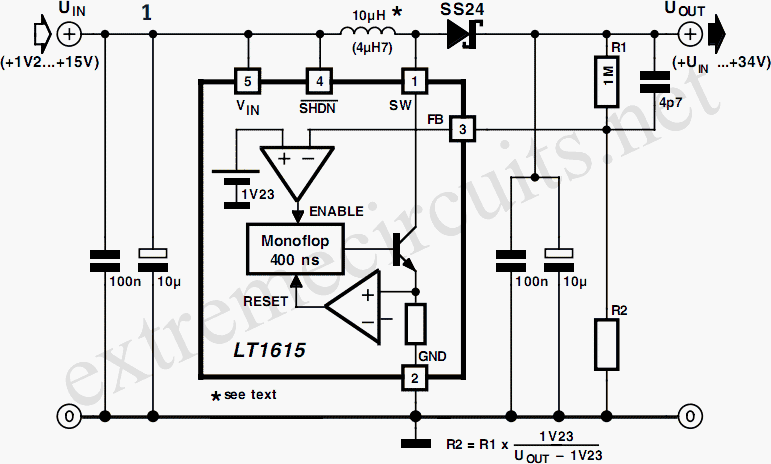
A DC/DC converter IC from Linear Technology, the LT1615 step-up switching voltage regulator, is capable of generating an output voltage of up to +34V from a supply voltage ranging from +1.2V to +15V, utilizing only a few external components....
The circuit presented here can convert a single-ended supply voltage into a balanced set of supply voltages. This is achieved without the use of difficult-to-obtain, exotic integrated circuits. All components utilized in the circuit are common and likely available...