
VGA to BNC Adapter Converter circuit
The circuit is designed to interface with monitors that accept composite sync on green, which is common in certain professional and industrial displays. The use of AC-coupling capacitors is critical in ensuring that the VGA output does not send any DC voltage to the monitor, which could potentially damage both the VGA card and the monitor. The BS170 MOSFET provides a means of grounding the green output, which is essential for achieving the correct sync signal.
In scenarios where the green component is at its maximum, care must be taken to adjust R2 to prevent synchronization issues. This adjustment must be done with consideration of the overall brightness and load on the graphics card, as it can affect the performance of the display. The circuit's design allows for easy modification of the resistor values to maintain color balance, which is crucial for accurate color representation.
The integration of the 74HC86 EXOR gate facilitates the combination of V-sync and H-sync signals, making it a vital component of the circuit. The design accounts for the differences in sync signal polarity between DOS and Windows operating modes, ensuring compatibility across different platforms. The inclusion of a jumper (JP1) for mode selection allows users to easily switch between configurations.
The compact PCB design is intended for efficient use of space, making it suitable for installation in smaller enclosures. The use of a 78L05 voltage regulator ensures that the circuit operates reliably across various power supply inputs, while the protective features, such as the reverse polarity diode and power indicator LED, enhance the robustness of the design. Overall, this circuit provides a reliable solution for connecting VGA outputs to monitors with composite sync on green, ensuring stable performance and flexibility in operation.There are monitors which only have three BNC inputs and which use composite synchronization (sync on green`). This circuit has been designed with these types of monitor in mind. As can be seen, the circuit has been kept very simple, but it still gives a reasonable performance. The principle of operation is very straightforward. The RGB signals fro m the VGA connector are fed to three BNC connectors via AC-coupling capacitors. These have been added to stop any direct current from entering the VGA card. A pull-up resistor on the green output provides a DC offset, while a transistor (a BS170 MOSFET) can switch this output to ground. It is possible to get synchronisation problems when the display is extremely bright, with a maximum green component.
In this case the value of R2 should be reduced a little, but this has the side effect that the brightness noticeably decreases and the load on the graphics card increases. To keep the colour balance the same, the resistors for the other two colors (R1 en R3) have to be changed to the same value as R2.
An EXOR gate from IC1 (74HC86) combines the separate V-sync and H-sync signals into a composite sync signal. Since the sync in DOS-modes is often inverted compared to the modes commonly used by Windows, the output of IC1a is inverted by IC1b.
JP1 can then by used to select the correct operating mode. This jumper can be replaced by a small two-way switch, if required. This switch should be mounted directly onto the PCB, as any connecting wires will cause a lot of interference. The PCB has been kept as compact as possible, so the circuit can be mounted in a small metal (earthed!) enclosure.
With a monitor connected the current consumption will be in the region of 30 mA. A 78L05 voltage regulator provides a stable 5 V, making it possible to use any type of mains adapter, as long as it supplies at least 9 V. Diode D2 provides protection against a reverse polarity. LED D1 indicates when the supply is present. The circuit should be powered up before connecting it to an active VGA output, as otherwise the sync signals will feed the circuit via the internal protection diodes of IC1, which can be noticed by a dimly lit LED.
This is something best avoided. 🔗 External reference
Related Circuits
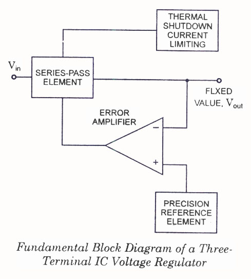
IC Voltage Regulators - Circuit diagram and block diagram of linear, fixed, adjustable (positive and negative), and switching voltage regulators. IC voltage regulators are essential components in electronic circuits, providing stable output voltages from a varying input voltage source. They...
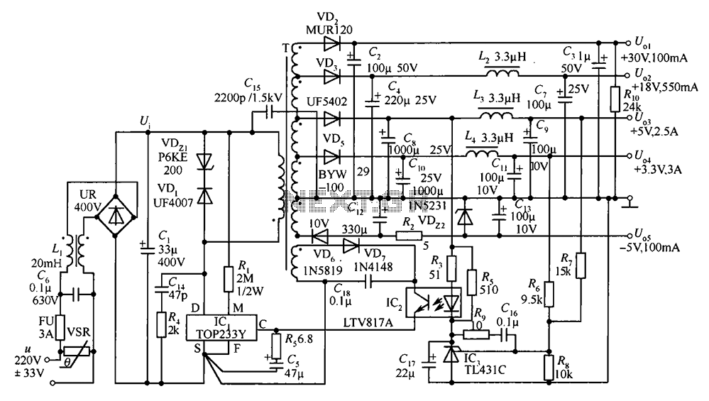
A 35W switching power supply circuit designed for a set-top box output is depicted in Figure 5. It features five distinct voltage outputs: Uo1 (+30V, 100mA), Uo2 (+18V, 550mA), Uo3 (+5V, 2.5A), Uo4 (+3.3V, 3A), and Uo5 (-5V, 100mA)....
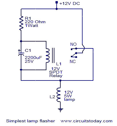
This is a simple lamp flasher circuit that utilizes only three components (a capacitor, a relay, and a resistor) in addition to the lamp. The operation of the circuit is straightforward. When power is turned on, the capacitor C1...
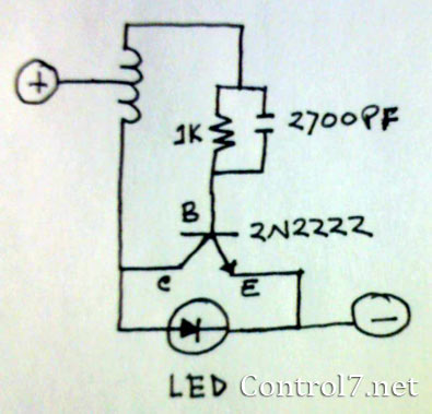
The LED is a fascinating component for amateur electronics hobbyists. The primary characteristic of an LED is that it requires a minimum of 3 volts to illuminate. Various circuits have been discovered to drive an LED using a single...
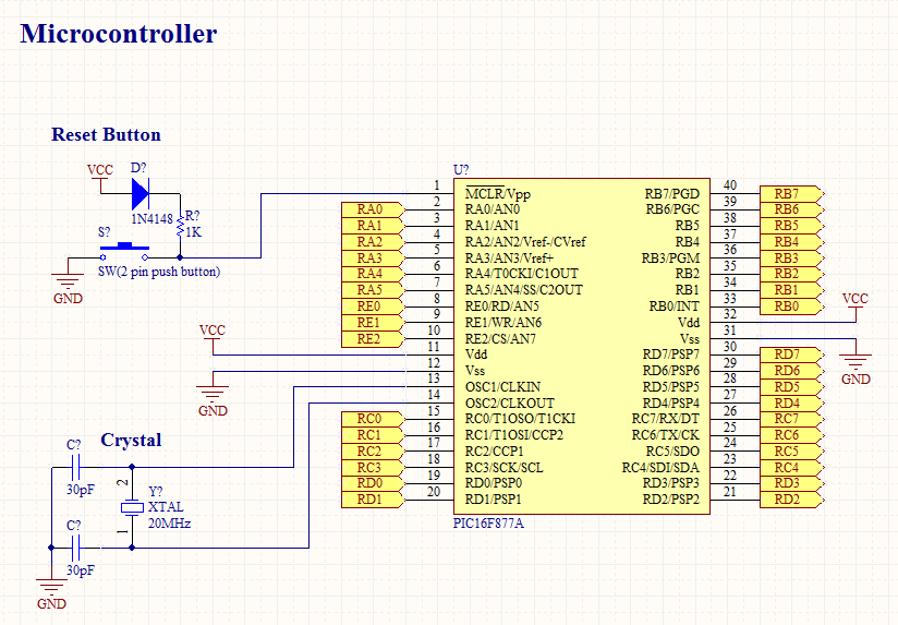
To operate a microcontroller, basic components are required to support its functionality, which is referred to as a basic circuit. The components needed are common and readily available at any electronics store. This document presents the schematic of a...
The circuit consists of a series of dual power supplies, providing a symmetrical ±15V supply for linear circuits. The same principle is applicable to non-symmetrical supplies, such as 5.0V and -12V regulators, which are used in applications like registers....