
HF VHF receiver diplexer
The proposed diplexer design serves as a critical component for optimizing the performance of the Icom PCR-1000 receiver across different frequency bands. The back-to-back low-pass and high-pass filter configuration ensures that signals from the K9AY antenna are effectively routed to the receiver for frequencies below 30 MHz, while the discone antenna handles frequencies above this threshold without interference. This design not only improves convenience by eliminating the need for manual antenna switching but also enhances signal clarity and reception quality.
In constructing the diplexer, careful selection of components is essential. The use of capacitors in parallel to achieve specific capacitance values allows for flexibility when sourcing components, especially since certain values may not be readily available. The choice of a 50-ohm impedance throughout the system is crucial to minimize signal reflections and ensure efficient power transfer.
The circuit board layout is another critical aspect of the design. A compact and well-organized layout will help reduce parasitic capacitance and inductance, which can adversely affect the performance of the filters, especially at higher frequencies. It is advisable to keep traces short and utilize ground planes to maintain signal integrity.
The RF connectors selected for the diplexer should be of high quality to withstand the demands of VHF/UHF applications. BNC connectors are a common choice due to their reliability and ease of use, while type N connectors provide superior performance at higher frequencies, making them suitable for more demanding applications.
In summary, the construction of an HF/VHF diplexer for the Icom PCR-1000 receiver involves careful design considerations, including filter configuration, component selection, and circuit board layout, all aimed at achieving optimal performance across the desired frequency range.An Icom PCR-1000 listening to various MF, HF and VHF radio stations. However, there is a slight problem. Very slight, almost too small to even mention, more of an inconvenience than a problem. Still, if I am being inconvenienced, than others are too. This issue is with the antennas. My K9AY antenna works wonderfully from 500 KHz to 25 MHz or so. My discone antenna works wonderfully from about 30 MHz all the way up to about 1 GHz. In order to enjoy the full range of the receiver, I need to switch antennas. I have a small switch on my desktop, but it seems inconvenient to reach over and switch it when going from the AM band to the FM band or something similar. Therefore, I have decided that I need an HF/VHF receiver diplexer. One would think that such hardware is ready made for such instances. However, nothing I could find commercially would do the trick. Thus, since I could not buy one, I decided to build one to add to my collection of receiver doo-dads and nick knacks.
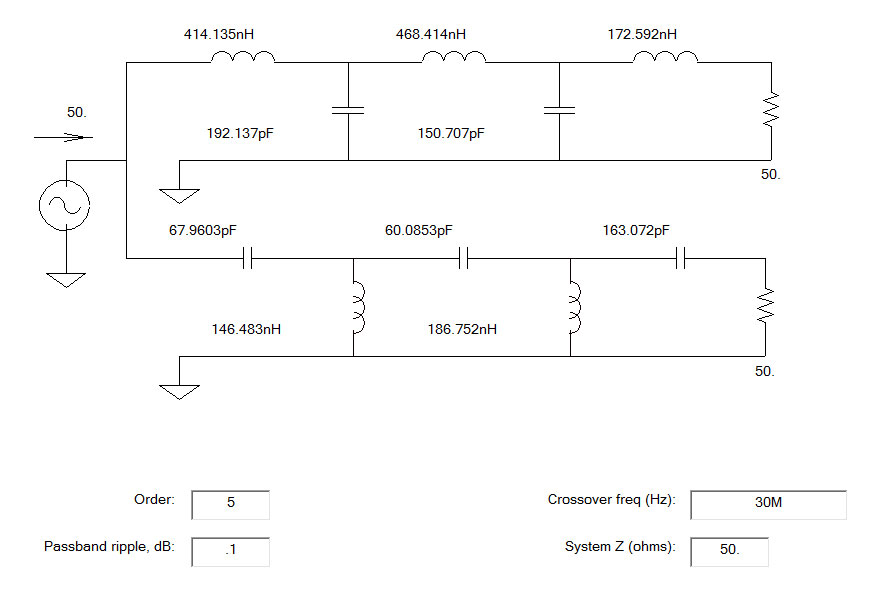
The design is relatively easy, a back to back low pass/high pass filer system with a 50 ohm impedance throughout. Something with a sharp cut off around 30 MHz or so: Then it comes down to the building. Since this is going to be used in the UHF range, care and attention needs to be paid to the layout of the components and the design of the circuit board.
Some of those capacitance values are not standard, however, by using two capacitors in parallel, one can get pretty close. Since this is going to be used for receiving only, I may be splitting hairs, however, I have found that well designed and built equipment is worth the extra effort.
As one may be able to discern, C2 and C3 are in parallel to make 192 PF, C5 and C6 are in parallel to make 60 PF, and C7 and C8 are in parallel to make 163 PF. The input and output RF connectors are whatever the builder wants to use, however, I would recommend at least BNC or type N for the VHF/UHF side.
My unit has all type BNC female connectors. Parts list: 🔗 External reference
Related Circuits
The circuit operates at a voltage of 9V with a current consumption of only 5mA. It allows for frequency adjustment within the range of 150 to 180 kHz, featuring a bandwidth of approximately 20 kHz. This configuration ensures that...
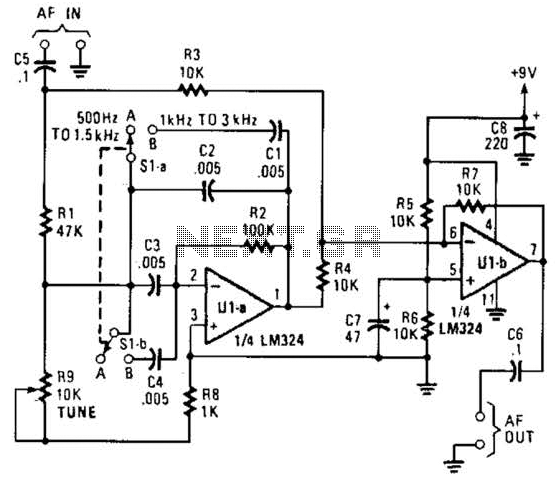
The notch filter can be integrated into nearly any receiver to attenuate a specific frequency by over 30 dB. This filter is particularly useful for diminishing heterodynes and whistles. A notch filter, also known as a band-stop filter, is designed...
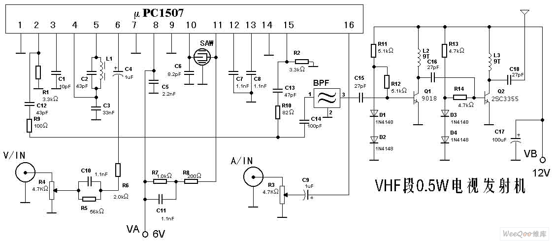
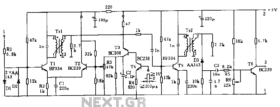
The TV transmitter described here is capable of transmitting audio and video signals from satellite television receivers, VCD players, and video recorders through an open circuit. It can also receive signals using open antennas. This device is ideal for...
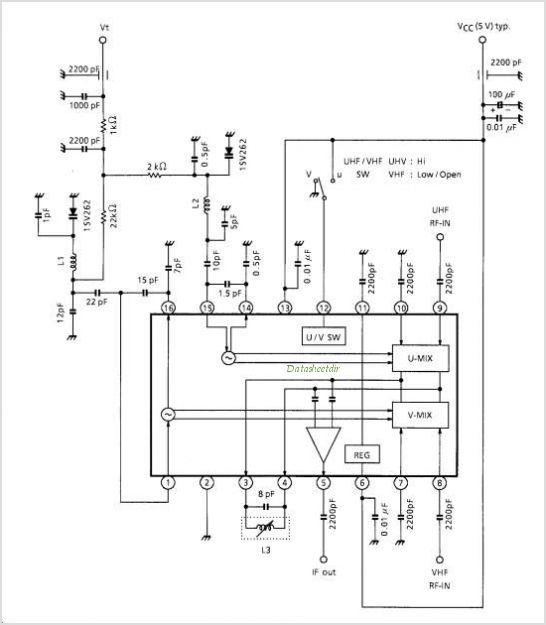
TA1317ANG is a deflection processor integrated circuit (IC) designed for large and wide picture tubes. It includes an electronic width (EW) correction circuit, a vertical distortion correction circuit, and a dynamic focus correction circuit. The device can control various...
It is important to recognize that the EC10 is a vintage receiver with collector appeal. Any modifications should aim to preserve its original state, and most of the following suggestions adhere to this principle. While replacing all Germanium transistors...
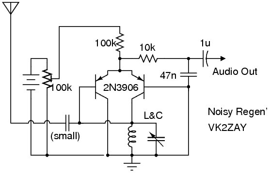
The following circuit illustrates a Noisy Regenerative Receiver Circuit Diagram. Features include a Noisy Regenerative Receiver Circuit, which simplifies the process of... The Noisy Regenerative Receiver Circuit is designed to amplify weak radio frequency signals while also incorporating a regenerative...