
Detected distance with ultrasonic receiver circuit diagram
The described circuit is designed for ultrasonic signal detection and amplification, primarily utilized in applications such as proximity sensing or object detection. The 9V power supply ensures a low power consumption of 5mA, making it suitable for battery-operated devices. The adjustable frequency range of 150 to 180 kHz allows for flexibility in various operational environments, accommodating different ultrasonic signals.
The bandwidth of approximately 20 kHz is critical for filtering out noise and ensuring that only relevant ultrasonic pulses are processed. The design includes a pulse-width filter, which only allows pulses wider than 70 microseconds to be amplified, thereby enhancing the circuit's selectivity and sensitivity.
The integration of diodes D1 and D2 serves to protect the transistor T1 from high voltage spikes that could occur during signal detection, ensuring reliable operation. The configuration of transistors T1 and T5 as high-frequency amplifiers allows for effective signal amplification, which is crucial for detecting weak ultrasonic signals.
The threshold switch controlled by rectifier D3 and adjustable via resistor R6 enables the user to set the sensitivity of the circuit, allowing it to adapt to different environments or signal strengths. The additional transistors T2, T3, and T4 provide further amplification and control, ensuring that the output signal is robust enough for subsequent processing or triggering of other devices.
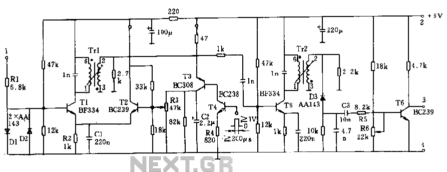
The transformer winding data indicates a careful consideration of inductance and impedance matching for optimal performance, with the use of 0.03 mm copper wire ensuring minimal resistive losses. The winding ratios suggest a design focused on achieving the necessary voltage levels for effective signal processing. Overall, this circuit is a well-engineered solution for applications requiring precise ultrasonic detection and amplification.The circuit voltage 9V, current consumption is only 5mA, the home can be adjusted within the range of 150 ~ 180kHz frequency, a bandwidth of about 20kHz, to ensure that only wider than 70us pulse to pass and be amplified. The receiver input terminal is directly connected to the sensor, and thus that is connected to the oscillator. In the event of an ultrasonic pulse, the signal voltage at the base of T1 by the diodes D1, D2 limit to a lower value.
Transistors T1 and T5 constitute two high-frequency amplifier, and then by the rectifier D3, as threshold switch control output transistors T6, the threshold adjustment by R6. Transistors T2, T3, T4 as an additional stage for controlling the first high frequency stage. Transformer winding data: end 6 to 1: 200 turns, 0.03mm copper wire; end 3 ~ 2: 95-turn, 0.03mm copper wire.
Related Circuits
There is a modification to the RC delay circuits that some may want to consider. If a shorter discharge time is desired, this modification enables the circuit to restart more quickly. The modification to the RC delay circuit involves adjusting...
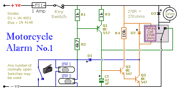
This circuit includes a timed output and an automatic reset feature. It can be manually operated using a key switch or a concealed switch. By incorporating an external relay, the circuit will automatically engage or immobilize the machine each...
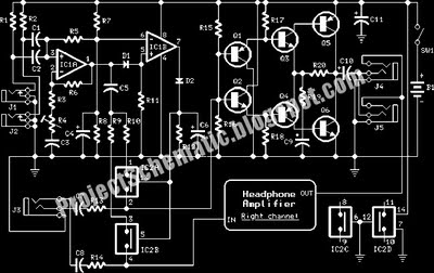
This is a complete circuit designed for an intercom system, which is illustrated in the accompanying diagram. The circuit utilizes a microphone amplifier based on IC1A, featuring two integrated circuits: the LM358, a low-power dual operational amplifier, and either...
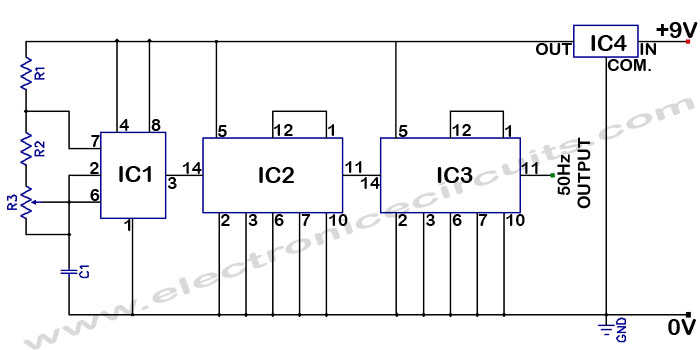
Accurate 50Hz Oscillator Circuit Using 555 and 7490. This circuit generates a 50Hz pulse. It consists of a 555 timer and two 7490 divide-by-ten counters. The circuit utilizes a 555 timer configured in astable mode to produce a square wave...
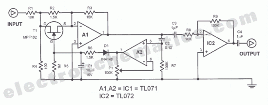
The function of this automatic volume control circuit is to amplify signals without distorting their dynamic compression. The amplitude differences in the signal are leveled off, eliminating disturbing effects. This technique avoids overcompensation in volume. The circuit is utilized...
LCD modules have become a popular means of displaying system messages and status in embedded applications. This application note demonstrates how to interface an SST FlashFlex microcontroller to a typical character LCD module. The SST FlashFlex is an industry-standard,...
Warning: include(partials/cookie-banner.php): Failed to open stream: Permission denied in /var/www/html/nextgr/view-circuit.php on line 713
Warning: include(): Failed opening 'partials/cookie-banner.php' for inclusion (include_path='.:/usr/share/php') in /var/www/html/nextgr/view-circuit.php on line 713