
Audio Compressor Circuit
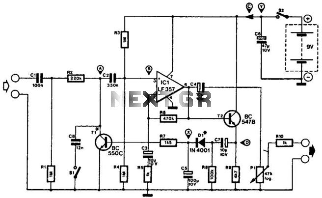
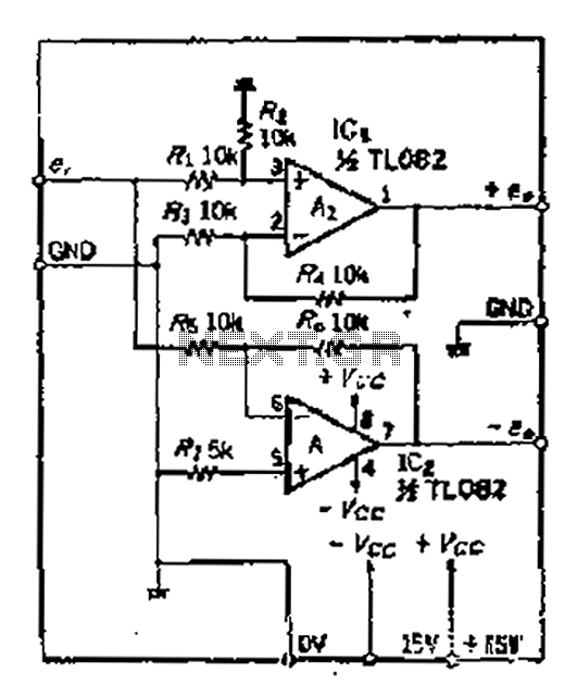
The described compressor circuit is designed to handle audio signals effectively by compressing low-level signals (25 mV p-p) to a much higher output level (20 V p-p). This capability is particularly useful in various audio processing applications, where maintaining signal integrity while adjusting levels is crucial. The input range of 1.5 V p-p to 3.5 V p-p allows for a wide variety of signal sources, ensuring compatibility with different audio equipment.
The frequency response of the compressor spans from 7 Hz to 67 kHz, indicating its ability to handle both low-frequency sounds, such as bass, and high-frequency sounds, including treble. This broad frequency range makes it suitable for high-fidelity audio applications, ensuring that the compressor does not introduce significant distortion or loss of quality to the audio signal.
In practical applications, this compressor can be integrated into audio mixing consoles, broadcasting equipment, or communication devices where dynamic range control is necessary. The design may include operational amplifiers configured in a feedback loop to achieve the desired compression characteristics, along with components such as resistors, capacitors, and diodes to shape the frequency response and ensure stability.
The implementation of this compressor circuit can enhance audio clarity, prevent clipping during loud passages, and improve overall sound quality in both live and recorded environments. The versatility of this device makes it an essential component in modern audio processing systems. This compressor will compress a 25-mV p-p to 20-V p-p audio output to input levels remaining between 1.5 V p-p to 3.5 V p-p, and has a frequency response of 7 Hz to 67 kHz. It is suitable for audio and communications applications. 🔗 External reference
Related Circuits
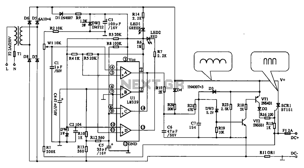
The Chizuru 100Hz channel frequency pulse charging circuit for electric bike batteries is designed to manage the charging process efficiently. It features a step-down transformer (Tl) and a bridge rectifier formed by diodes D5 to D8. The output ripple...
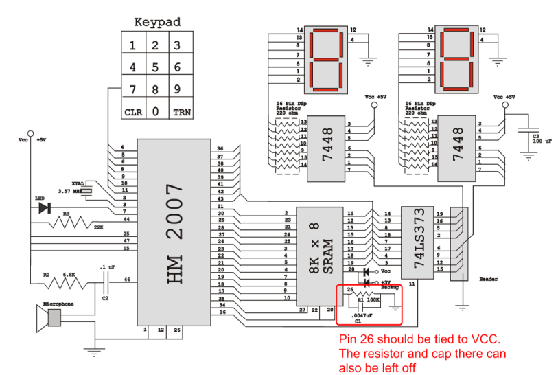
Verify the pin configurations on the datasheets for the integrated circuits used in your project, making necessary adjustments. In this instance, the RAM chip utilized had a non-inverted enable signal on pin 26, while the schematic assumed it was...
The core of the circuit is a two-transistor flasher with frequency modulation applied to the base of the first transistor. When the pushbutton is pressed, the oscillation frequency increases to a peak, and upon release, the frequency decreases due...

This is an application circuit for calibration known as a high voltage AC calibrator circuit. An essential aspect of sine wave oscillator design is the stable control of amplitude. This circuit not only stabilizes the amplitude through servo control...
A balanced output is often associated with the positive phase amplifier output terminal of an operational amplifier, which is typically viewed as the inverting amplifier circuit. However, the reversed phase output can lead to a loss of balance in...
Two circuits for laser transmitters are described. The first circuit utilizes a simple laser pointer module, with 3 or 5mW devices functioning effectively. Higher power units are often imported from the USA or Hong Kong compared to UK approved...
Warning: include(partials/cookie-banner.php): Failed to open stream: Permission denied in /var/www/html/nextgr/view-circuit.php on line 713
Warning: include(): Failed opening 'partials/cookie-banner.php' for inclusion (include_path='.:/usr/share/php') in /var/www/html/nextgr/view-circuit.php on line 713