
Stereo Noise Reduction Circuit
The noise reduction circuit operates on the principle of detecting silence or low audio signals, which are typically the moments when unwanted noise becomes noticeable. The circuit employs a combination of analog and digital components to achieve effective noise suppression.
At its core, the circuit includes a signal detection module that monitors the audio input for periods of low amplitude. When the input signal falls below a predetermined threshold, the circuit activates a variable gain amplifier (VGA) or a digital signal processor (DSP) that reduces the output signal level. This attenuation can be adjusted based on the severity of the noise detected, allowing for a customizable response to different audio environments.
In addition to the VGA or DSP, the circuit may incorporate a low-pass filter to further refine the audio signal by removing high-frequency noise components that can be particularly intrusive during silent periods. The filter's cutoff frequency can be tailored to suit the specific application, ensuring that the desired audio quality is maintained even while noise reduction is active.
Feedback mechanisms can also be integrated into the design to monitor the effectiveness of the noise reduction process. This feedback loop can help optimize the attenuation levels dynamically, ensuring that the circuit responds appropriately to varying audio conditions.
Power supply considerations are crucial for the circuit's performance. A regulated power supply is recommended to ensure consistent operation, particularly in environments with fluctuating voltage levels. Furthermore, careful selection of components, such as low-noise operational amplifiers, can significantly enhance the overall performance of the noise reduction circuit.
Overall, this noise reduction circuit is a valuable addition to audio systems, providing a smoother listening experience by effectively managing unwanted noise during quiet moments in music playback.The noise reduction circuit is based on the observation that noise is always disturbing in intervals when music stops. It will attenuate the signal output.. 🔗 External reference
Related Circuits
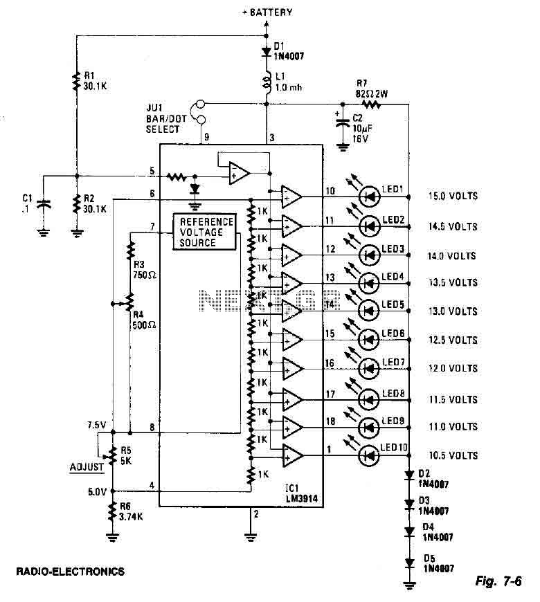
This screen utilizes ten LEDs to indicate a voltage range from 10.5 to 15 volts, with each LED corresponding to a 0.5-volt increment. The core component of the circuit is the LM3914 LED bar graph/display driver. A trimming potentiometer,...
The antenna tuning circuit can accommodate 1/2 wave length antennas or higher, for input resistances of 50 Ohms which make it suitable for CB (Citizen Band) transceivers. C1 is for fine tuning and C2 is just for tuning. Turning...
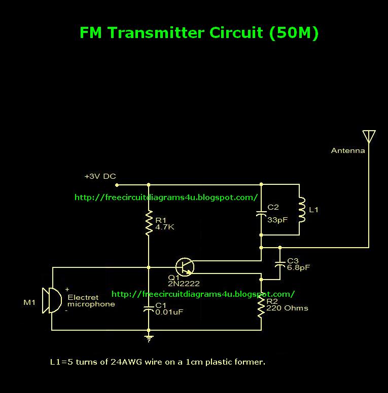
This is an FM transmitter circuit diagram. This circuit uses a 2N2222 transistor, allowing it to operate at 3V and transmit signals up to 50 meters. The FM transmitter circuit consists of several key components, primarily centered around the 2N2222...
This circuit provides a straightforward and efficient method for interfacing two relays in switching applications. The relay driver utilizes a standard BC547 NPN transistor (or equivalent) to enhance the input impedance. It is a widely used driver capable of...
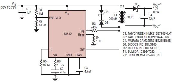
A straightforward dual 15-volt power supply electronic circuit can be created using the LT3512 switching regulator IC produced by Linear Technology. This basic 15-volt DC power supply operates with an input voltage range of 36 to 72 volts and...
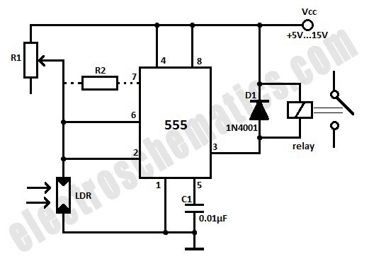
This light-activated relay circuit utilizes the 555 timer integrated circuit (IC) and a light-dependent resistor (LDR) to create a light-sensitive relay suitable for applications such as intruder alarm systems or automatic lamp control at sunset and sunrise. The potentiometer...