
Tone encoder
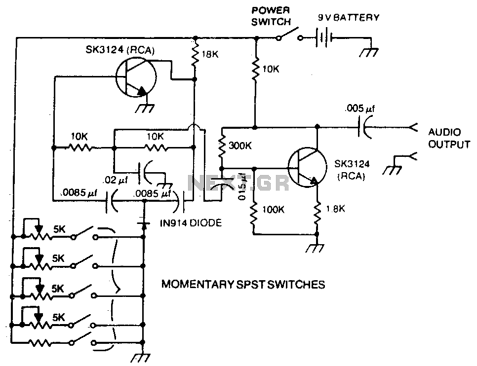
The twin-T oscillator circuit is a well-known electronic configuration used for generating audio tones and frequencies. It typically consists of two resistors and two capacitors configured in a specific manner to create a notch filter that defines the frequency of oscillation. The output frequency is determined by the resistor and capacitor values, allowing for precise tuning of the desired tone.
In this circuit, the pushbuttons serve as momentary switches that activate the oscillator when pressed. Upon pressing a button, the circuit completes and the twin-T oscillator begins to produce a tone at the set frequency. Once the button is released, the circuit is interrupted, ceasing the tone generation. This functionality is ideal for applications such as sound effects in musical instruments or alert systems.
To implement this circuit, the resistors are typically connected in parallel with the capacitors, forming a feedback loop that sustains oscillation. The values of these components must be chosen carefully to achieve the desired frequency range. For example, using higher resistor values and lower capacitor values will result in higher frequencies, while lower resistor values and higher capacitor values will yield lower frequencies.
The output of the twin-T circuit can be connected to a speaker or an audio output device to produce audible tones. Additional components, such as amplifiers, may be incorporated to enhance the output signal for better sound quality. This circuit configuration allows for versatility in tone generation, making it suitable for various electronic projects and applications.A basic twin-T circuit uses resistors for accurately setting the frequency of the output tones, selected by pushbutton Momentary switches produce a tone only when the button is depressed. 🔗 External reference
Related Circuits
The LM1036 is a DC-controlled tone (bass/treble), volume, and balance circuit designed for stereo applications in car radios, televisions, and audio systems. The LM1036 integrates several essential audio control functions into a single chip, making it suitable for various audio...
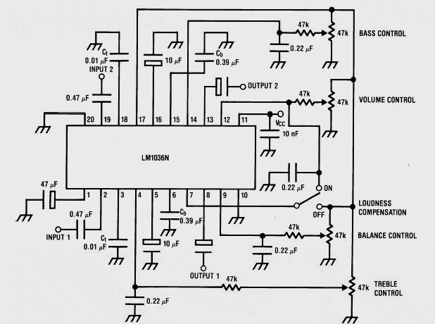
This weblog discusses electronic circuit schematics, PCB design, DIY kits, and electronic project diagrams. It features a stereo tone control circuit built using the LM1036 integrated circuit (IC). This control circuit adjusts bass, treble, volume, and the balance between...
Upon acquiring the car, it was appreciated that it did not emit a "chirp" or sound the horn each time the doors were locked or unlocked. There are occasions when discreetness is preferred regarding entering or exiting the vehicle....
The following circuit illustrates a Bass and Treble Controller Circuit. This circuit is constructed based on the classic Baxandall tone control circuitry. The Bass and Treble Controller Circuit is designed to adjust the low and high-frequency response of audio signals,...
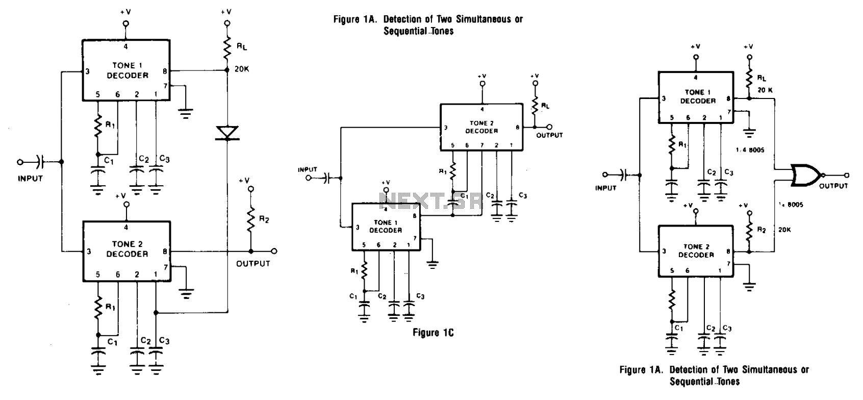
Two integrated tone decoders, XR-567 units, can be connected to allow for the decoding of simultaneous or sequential tones. Both units must be activated before an output is produced. Resistors R1 and R'1, along with capacitors C1 and C'1,...
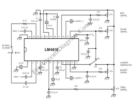
The LM4610 utilizes a DC signal to manage the tone (bass/treble), volume, and balance circuits. The benefits of employing DC control include the ability to operate in mono mode. The LM4610 is an integrated circuit designed for audio applications, specifically...