
High and low frequency signal generator circuit diagram
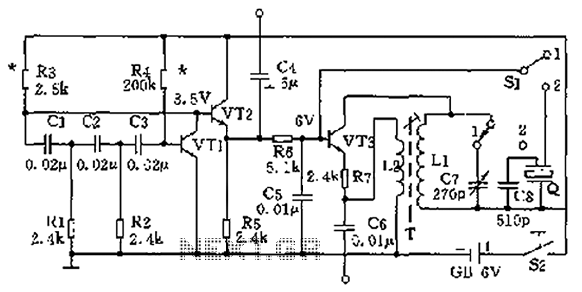
The high-frequency signal generator circuit operates by utilizing a combination of transistors, capacitors, and inductors to create oscillations at specified frequencies. The transistors (VT1 to VT3) serve as the main amplification elements, allowing for the generation of the desired frequency signals. The choice of transistors such as the 3DGl00 or 3DG201 ensures that the circuit can operate efficiently at high frequencies while maintaining low power consumption.
The capacitors play a critical role in determining the frequency response of the circuit. C7, with its dual configuration options, allows for fine-tuning of the oscillation frequency. The oscillation transformer, constructed with L1 and L2, is essential for coupling the generated signal and ensuring stability in the oscillation process. The specified number of turns in the inductors (100 for L1 and 35 for L2) is crucial for achieving the desired inductance values, which directly influence the frequency characteristics of the circuit.
Capacitor C8, being a mica capacitor, is chosen for its stability and low loss characteristics, which are important for maintaining signal integrity at high frequencies. The inclusion of three-stage ceramic filters for the 465 kHz IF signal enhances the selectivity and minimizes interference from unwanted signals, ensuring that the output is clean and usable for radio applications.
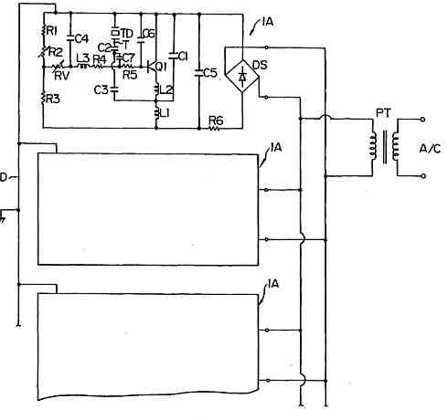
The optional DPDT switch (S1) provides versatility in circuit operation, allowing users to toggle between different modes or outputs as needed. This feature is particularly beneficial for experimentation and debugging purposes, enabling users to assess the performance of various configurations without the need for extensive rewiring. Overall, this high-frequency signal generator is an invaluable tool for both novice and experienced electronics enthusiasts, facilitating the exploration and repair of radio frequency circuits. As shown in the high-frequency signal generator capable of generating a low frequency 1kHz, 465kHz IF signal and the high frequency of 525 ~ 1605kHz, to repair radios or other circuit debugging very helpful for beginners production. Transistor VTl ~ VT3: choice 3DGl00,3DG201 other high-frequency low-power silicon tube, fT 100MHz, values between 50 and 100. C7 can be used 7/270pF radio with double or single row of capacitors connected capacitors. Oscillation transformer T can be carried out in radio in the week on the restructuring, on the core with a high strength wire 0.08mm around Ll, 100 turns, L2,35 turns.
C8 510pF available mica capacitors. Q three-stage selection of 465kHz IF ceramic filters. Sl optional DPDT type switch. Other component values shown in Figure labels.
Related Circuits
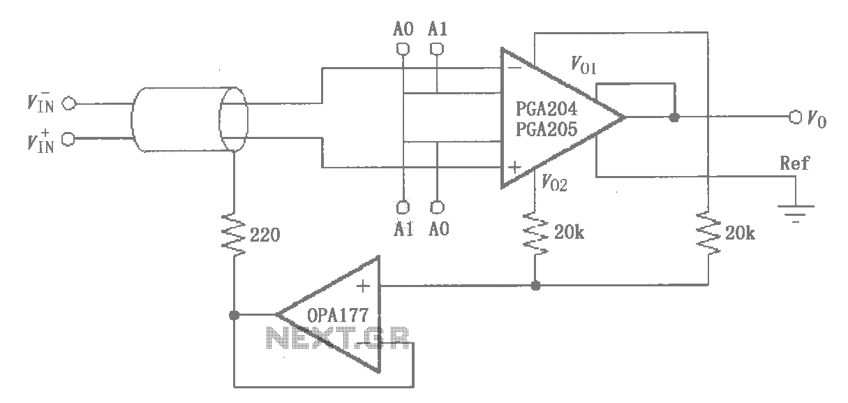
The circuit illustrated by the PGA204/205 pertains to the shield drive circuit shown in the figure. It is demonstrated through interference theory and practical application that the cable shield, when transmitting weak signals, maintains a certain potential. This configuration...
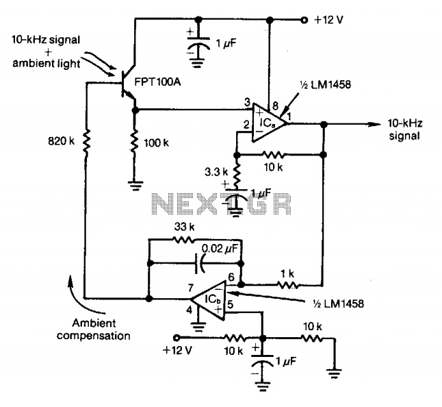
The feedback control of the phototransistor in this optical detector helps negate the effects of varying ambient light sources. The output of a modulated visible-light LED is detected, amplified, buffered, and fed through a low-pass filter. Ambient light signals...
This AC drill speed controller circuit schematic allows for the control of the drilling speed of a borer or drilling machine. This project is based on the principle that... The AC drill speed controller circuit is designed to modulate the...
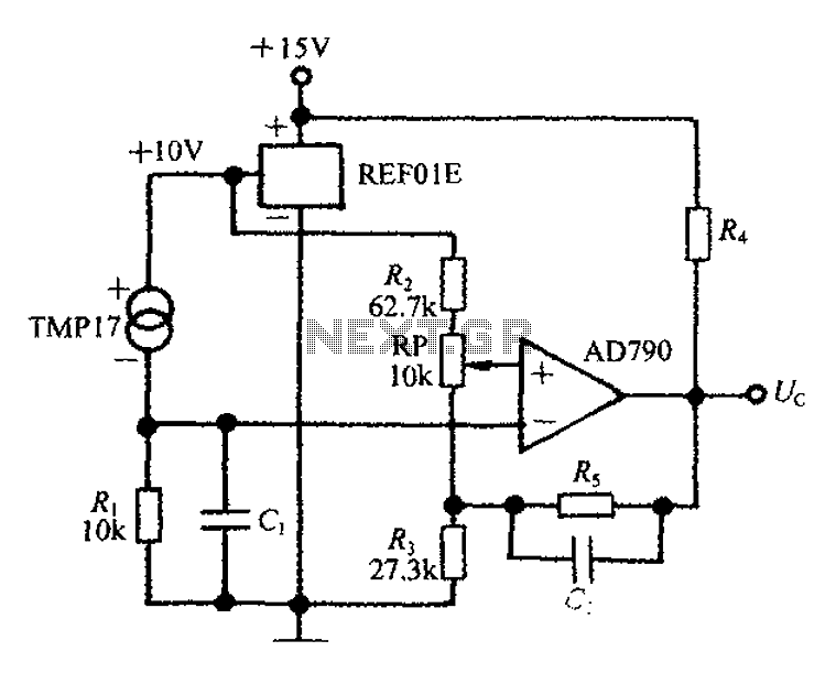
An adjustable thermostat controller circuit is widely used in everyday applications, such as for maintaining a constant temperature in soldering irons. The circuit utilizes the TMP17 sensor along with the REF01E voltage reference to ensure a stable 10V supply...
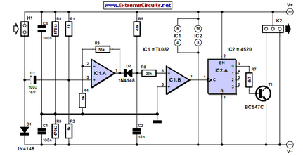
This circuit generates speed pulses from the speed-dependent voltage spikes produced by commonly used types of PC power supply fans, which are superimposed. The circuit utilizes the voltage spikes generated by the fan's operation to create a series of speed...
Ultrasonic atomizer circuit: How to generate an atomized water mist using ultrasonic sound waves. The ultrasonic atomizer circuit is designed to produce a fine mist of water by utilizing ultrasonic sound waves. This process involves the conversion of electrical energy...