
High And Low Voltage Cut Off With Time Delay
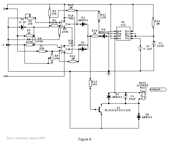
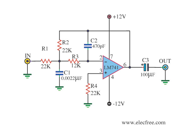
The power supply is a conventional type, as illustrated in Figure 1. Power is supplied through a step-down transformer (230/12-0-12V/500mA), and a bridge rectifier converts the AC input to DC. Two electrolytic capacitors are used to bypass any present voltage spikes, with the bridge capable of handling currents up to 1 Amp. A zener diode (D1) and its associated resistor (R1) are connected to the non-inverting terminal (+) of the 741 op-amp to provide a suitable reference voltage. The DC voltage from the sensor is fed to the inverting terminal (-) through a preset resistor (R2), which is used to set the input level. When the sensor input is below the zener voltage, the op-amp output remains high; when it exceeds the zener voltage, the output goes low. When the sensing voltage equals the zener voltage, the op-amp output is approximately zero. The op-amp operates as an inverting amplifier, where the zener and resistor network establishes the reference voltage at the inverting terminal. The sensing voltage, derived through a 10K preset resistor, is applied to the non-inverting terminal, establishing the high-level cut-off.
The circuit also includes a monostable configuration. The external timing capacitor (C2) is initially kept discharged by the timer. The circuit triggers upon receiving a pulse at pin 2 when the voltage reaches 1/3 Vcc. Once triggered, the circuit remains in this state until either the set time elapses or power is cut off. The delay period in seconds is calculated as 1.1 times C2 times R1, where R1 is in megohms and C2 is in microfarads. In practice, R1 should not exceed 20 MΩ, and if an electrolytic capacitor is used for C2, a low leakage unit should be selected. The time delay may need adjustment by varying R1 to accommodate the wide tolerance of electrolytic capacitors. Additionally, a relay (12V <500 ohms) is connected to the collector of the NPN transistor. The output voltage from the comparator is applied to the base of the NPN transistor through a resistor (R1). When the comparator output is low, the transistor remains in the OFF state, and the relay is de-energized.The power line fluctuations and cut-offs cause damages to electrical appliances connected to the line. It is more serious in the case of domestic appliances like fridge and air conditioners. If a fridge is operated on low voltage, excessive current flows through the motor, which heats up, and get damaged.
The under/over voltage protection circuit with time delay presented here is a low cost and reliable circuit for protecting such equipments from damages. Whenever the power line is switched on it gets connected to the appliance only after a delay of a fixed time.
If there is hi/low fluctuations beyond sets limits the appliance get disconnected. The system tries to connect the power back after the specific time delay, the delay being counted from the time of disconnection. If the power down time (time for which the voltage is beyond limits) is less than the delay time, the power resumes after the delay: If it is equal or more, then the power resumes directly.
This circuit has been designed, built and evaluated by me to use as a protector for my home refrigerator. This is designed around readily available semi-conductor devices such as standard bipolar medium power NPN transistor (D313/SL100/C1061), an 8-pin type 741 op-amp and NE555 timer IC.
Its salient feature is that no relay hunting is employed. This draw back is commonly found in the proctors available in the market. The complete circuit is consisting of various stages. They are: - Dual rail power supply, Reference voltage source, Voltage comparators for hi/low cut offs, Time delay stage and Relay driver stage. Lets now look at the step-by-step design details. This is a conventional type of power supply as shown in Figure 1. The power is applied through the step-down transformer (230/12-0-12V/500mA). The DC proportional to the charging input voltage is obtained from bridge rectifier. Two electrolytics are there to bypass any spikes present. Bridge is capable of handling currents up to 1 Amp. In this ckt the zener diode D1 and itG ™s associated resistor R1 are connected to the non-inverting terminal (+ve) of 741 to give the suitable reference voltage.
The DC voltage from the sensor is given to the inverting (-ve) terminal through pre-set R2. This is used to set the input level. When the sensor input is less than Zener voltage the output from the Op-amp remains high and when it is greater than Zener voltage the output goes low. When the sensing voltage is equal to Zener voltage the output of the op-amp is approximately zero. Here the op-amp is used as a inverted amplifier. See Figure 3. Zener and resistor network gives reference voltage to the inverting terminal (-ve) of op-amp. Sensing voltage derived through the 10 K pre-set is given to the non- inverting (+ve) terminal and this sets the high level cut.
When the input DC from the sensor is less than Zener voltage the output of the op-amp is low and vice-versa. When the input DC voltage is equal to the zener voltage, the op-amps output is approximately zero. This is basically a monostable. The external timing capacitor C2 is held initially discharged by the timer. The circuit triggers upon receiving a pulse to its pin 2 when the level reaches 1/3 Vcc. Once triggered. , the circuit will remain in that state until the set time is elapsed or power to the circuit cuts off.
The delayed period in seconds is 1. 1 C2. R1 where R1 is in megohms and C2 is in microfarads. In practice, R1 should not exceed 20 M. If you use an electrolytic capacitor for C2, select a unit for low leakage. The time delay may have to be adjusted by varying R1 to compensate for the wide tolerance of electrolytics. In this a relay (12V <500 ohms) is connected to the collector of NPN transistor. The out put voltage from the comparator is applied to the base of NPN transistor through a resistance R1.
When the output from the comparator is low the transistor is in OFF state and the relay is in de-e 🔗 External reference
Related Circuits
A low power, long-life LED flashlight circuit. Electronic Design proposed a simple circuit to resolve this in a recent article. The front end of their circuit draws less than a milliamp of extra current. The described LED flashlight circuit is...
For basic requirements, square wave inverters can be utilized as they are simple, low-cost, and easy to construct. However, pure sine wave inverters are preferred for driving inductive loads. This document discusses a simple low-power square wave inverter using...
This circuit is designed to delay the start of the cathode ray tube (CRT) sweep for an expanded display. It offers three range settings: 0 to 5 miles, 60 miles, and 200 miles. The circuit primarily utilizes a cathode-coupled...
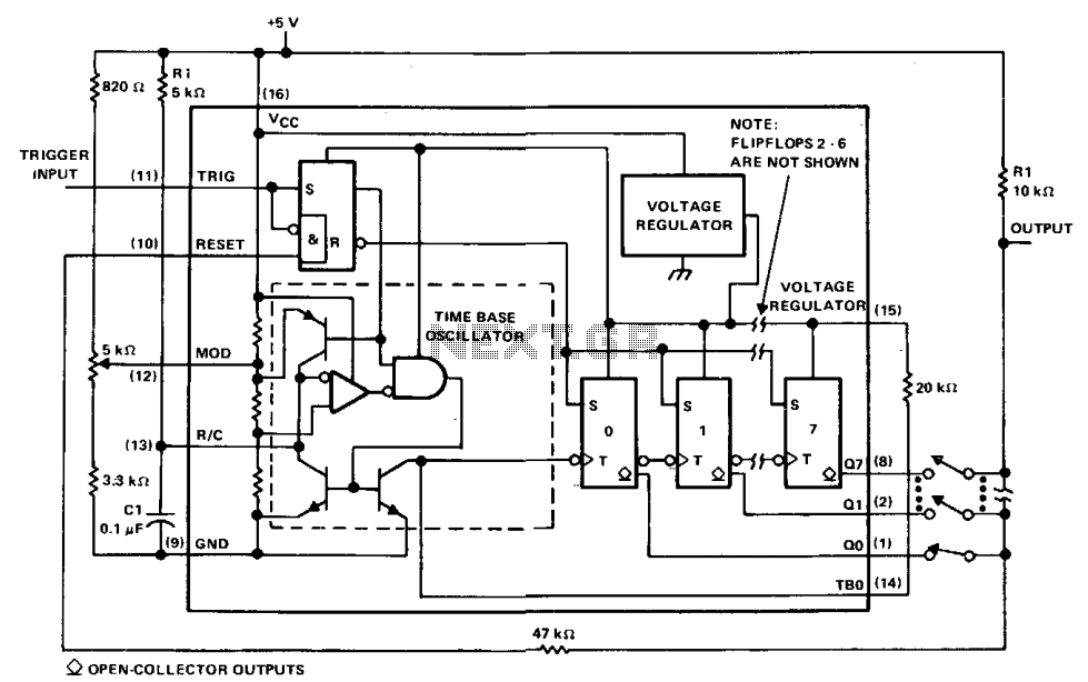
The µA2240 can be easily configured as a programmable voltage-controlled timer with a minimal number of external components. The modulation input (pin 12) allows for external adjustment of the input threshold level. A variable voltage is applied from the...

The PGA202 offset voltage correction circuit is designed to correct both input and output offset voltages. There are four different gain settings for the PGA202, which result in slight variations in input offset voltage. A 50k potentiometer is used...
This circuit filters low frequencies below 10 kHz using the highly popular operational amplifier IC uA741. It is convenient for applications that require the conversion of analog signals to digital or vice versa. In digital sound systems, this circuit...