
Low pass filter circuit 10KHz using uA741
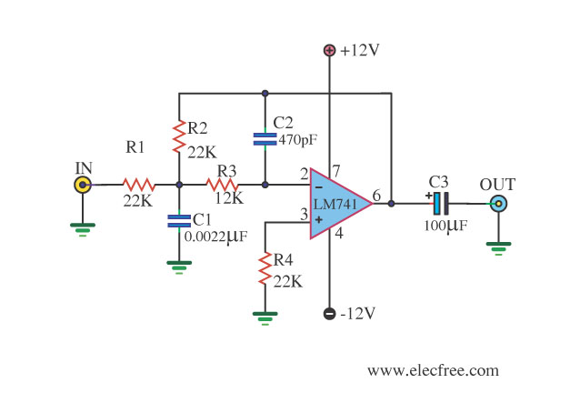
The Low Pass Active Filter circuit designed around the uA741 operational amplifier serves to effectively attenuate frequencies above the designated cutoff point, thereby allowing only lower frequencies to pass through. This is particularly useful in audio applications where unwanted high-frequency noise can interfere with the clarity of the sound. The uA741 is chosen for its reliability and performance in analog signal processing.
In constructing the circuit, the values of the resistors and capacitors are critical. By selecting equal resistor values (R1 and R2) and capacitor values (C1 and C2), the user can define the cutoff frequency with precision. The relationship between these components is governed by the formula for the cutoff frequency (fc), which can be expressed as:
fc = 1 / (2πRC)
Where R is the resistance and C is the capacitance. By manipulating these values, the designer can set the desired cutoff frequency to either filter out noise or to enhance the audio signal's quality.
The operational amplifier requires a dual power supply, which is essential for its proper functioning, especially when dealing with AC signals. The typical voltage range of +/- 5V to 18V allows for adequate headroom in signal processing, reducing the risk of clipping and distortion.
In summary, this Low Pass Active Filter circuit using the uA741 op-amp is a versatile tool for audio signal processing, providing a simple yet effective means of filtering out high-frequency noise while preserving the integrity of lower frequency signals. Its adjustable parameters make it suitable for various applications in sound systems and digital signal processing environments.This be the circuit filters 10KHz low size frequencies s use IC op-amp the highly popular number uA741. By this circuit convenients for to apply to input and output of the circuit changes analog signal be digital or the circuit changes digital signal be digital.
In sound system of digital for synthetic the voice or music give for make wave form ou tput the smooth. And press the noise that happen at output. When small-sized signal was managed with decrypt linear the size is 8 bit. When you want to filter low frequency gives can change only. I thinks the Low Pass Active Filter circuit help you. Because of it uses IC LM741, then usable easy follow circuit image. We can fix the frequency is cut off get, by equipment value R1=R2 = R, and C1=C2=C When fix give 50Hz frequencies low only that can change. Values Show be valuable about 0dB = 50Hz, -3dB = 250Hz, -50dB = 10kHz Then will see tall frequency 50Hz more cut give until less is finished.
This circuit should use dual power supply positive, negative, GND +/- 5V to 18V in order to get a signal that is appropriate most. 🔗 External reference
Related Circuits
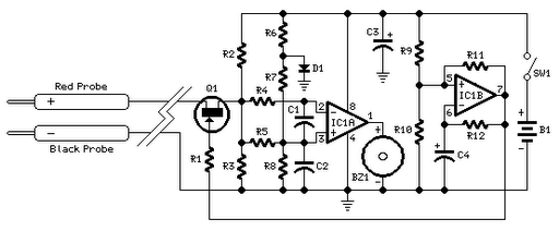
Short circuits or broken PCB tracks can be easily identified using a multimeter; however, this tool may yield inaccurate results when testing the efficiency of a transistor or diode unless the component is unsoldered and removed from the PCB....
A simple thermostat circuit can be utilized to control a relay, which in turn supplies power to a small space heater via the relay contacts. It is essential that the relay contacts are rated above the current requirements for...
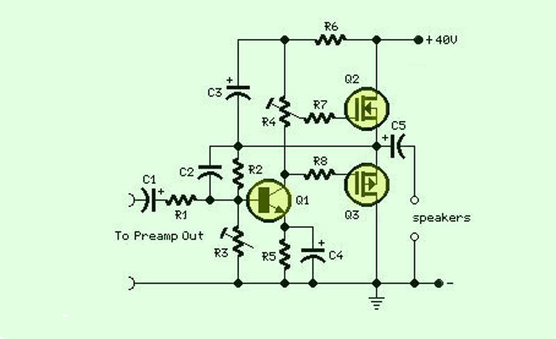
The function of this circuit is an audio amplifier capable of delivering a decent output power with a minimal number of components, with considerable efficiency. This audio amplifier circuit is designed to enhance audio signals, providing sufficient output power while...
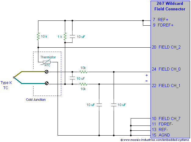
Filtering thermocouple wires ensures highly accurate temperature measurement by preventing noise pickup, decoupling thermocouple signals, and reducing measurement errors. A thermocouple noise filter circuit is effective in minimizing these errors. The implementation of a thermocouple noise filter circuit is essential...
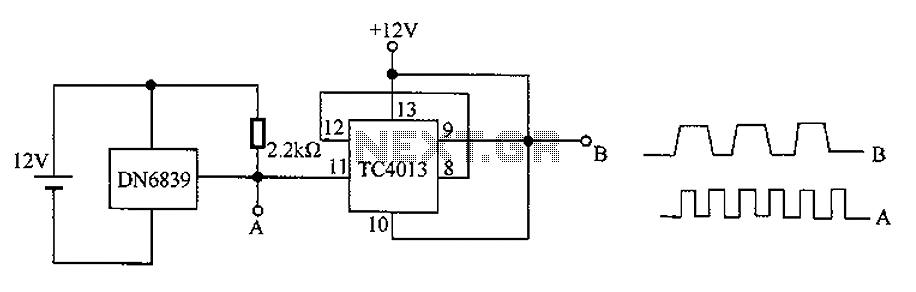
The circuit utilizes the integrated Hall element DN6839 for frequency division. It detects a magnetic field through the pulsating DN6839, generating a pulse waveform. The circuit is designed for applications involving very high-frequency pulsating magnetic fields. It employs the...
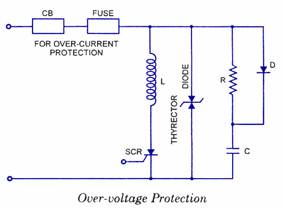
Silicon Controlled Rectifiers (SCRs) are sensitive to high voltage, over-current, and transients. To ensure satisfactory and reliable operation, they must be protected against such abnormal operating conditions. Due to the complexity and cost of protection mechanisms, devices with ratings...