
High drive oscillator-flasher
The described circuit employs a Schmitt trigger oscillator configuration, which is characterized by its ability to provide a clean, stable square wave output. The hysteresis introduced by resistors R1 and R2 ensures that the output transitions occur at distinct voltage levels, thus preventing noise from causing unintended switching. The feedback loop, formed by R3 and C, establishes the timing characteristics of the oscillator, determining the frequency of oscillation based on the RC time constant.
In this setup, R4 acts as a pull-down resistor, ensuring that the output is defined when the driver is not actively driving a load. This is particularly important in applications where the output may be left floating, as it prevents erratic behavior.
When R4 is replaced with an LED in conjunction with a current-limiting resistor, the circuit's functionality evolves. The LED will illuminate when the output is high, while the current-limiting resistor ensures that the LED operates within its safe current rating. The dual LED configuration allows for a visually engaging indicator, with the two LEDs flashing alternately due to the out-of-phase operation. This feature can be employed in various applications, such as decorative lighting, indicators, or alarms, where visual feedback is beneficial.
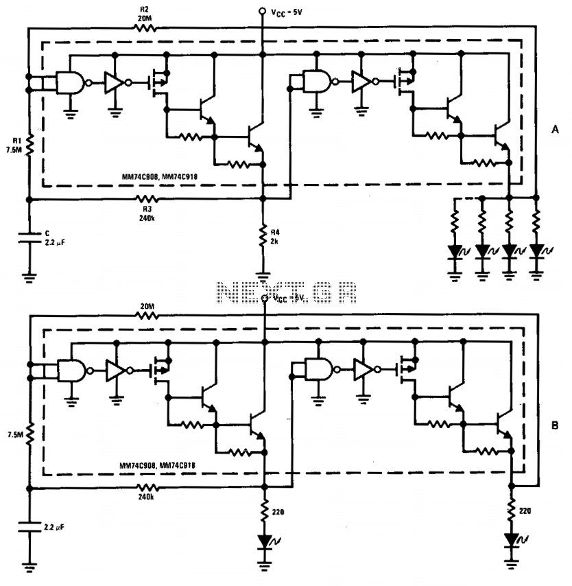
Overall, the circuit demonstrates versatility in its application, from basic LED driving to more complex signaling through phase-dependent flashing. The careful selection of component values will enable customization of the flashing rate and output characteristics to meet specific requirements.The driver in the package is connected as a Schmitt trigger oscillator (A) where R1 and R2 are used to generate hysteresis. R3 and C are the inverting feedback timing elements and R4 is the pull-down load for the first driver.
Because of its current capability, the circuit can be used to drive an array of LEDs or lamps. If resistor R4 is replaced by an LED (plus a current limiting resistor), the circuit becomes a double flasher with the 2 LEDs flashing out of phase (B). 🔗 External reference
Related Circuits
A minimum number of parts yields a compact switching converter that can provide sufficient voltage to drive white LEDs. The resulting lamp is much more efficient, in terms of lumen hours per pound of battery, than incandescent bulbs, and...
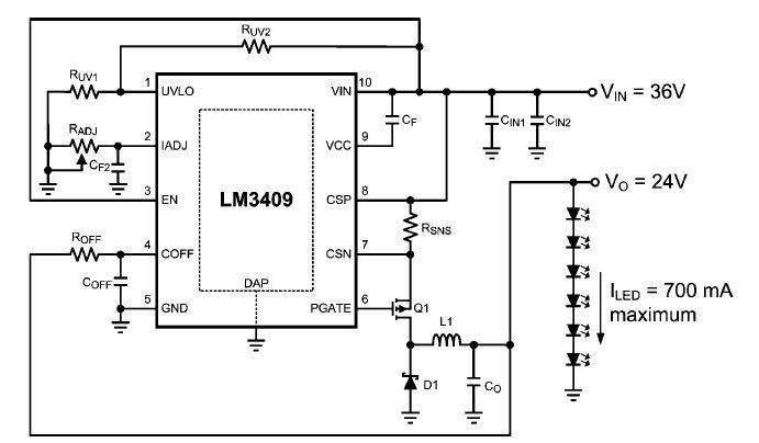
This dimming-controlled LED driver electronic circuit requires an input voltage of 36 volts and will provide an output voltage of 24 volts at a maximum current of 700 mA. The described dimming-controlled LED driver circuit is designed to efficiently convert...
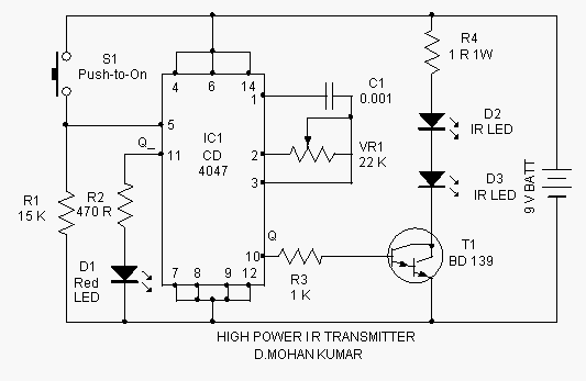
This infrared transmitter is capable of activating IR-based switching circuits from a distance of 10 meters or more. It features a high-power IR transmitter that drives two infrared LEDs. The infrared transmitter circuit is designed for remote activation of devices...
Power line fluctuations and cut-offs can damage electrical appliances connected to the line, particularly domestic appliances like refrigerators and air conditioners. When a refrigerator operates on low voltage, excessive current flows through the motor, leading to overheating and potential...

This is a simple nickel-cadmium (NiCd) battery charger powered by solar cells. A solar cell panel or an array of solar cells can charge a battery at more than 80% efficiency, provided the available voltage exceeds the fully charged...
This is a status panel driver circuit. This circuit is used to turn on lamps or LEDs in a graphic panel that represent faults, actions, and the status of an application. The status panel driver circuit is designed to control...