
High And Low Voltage Cut Off With Time Delay
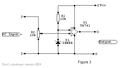
The power supply is a conventional type, as illustrated in Figure 1. Power is applied through a step-down transformer (230/12-0-12V/500mA). The DC voltage proportional to the charging input voltage is obtained from a bridge rectifier, which is capable of handling currents up to 1 Amp. Two electrolytic capacitors are included to bypass any present spikes. The circuit operates as a monostable; the external timing capacitor C2 is initially discharged by the timer. The circuit triggers upon receiving a pulse at pin 2 when the voltage level reaches 1/3 Vcc. Once triggered, the circuit remains in that state until either the set time elapses or power is cut off. The delay period in seconds is determined by the formula 1.1 C2 R1, where R1 is in megohms and C2 is in microfarads. In practice, R1 should not exceed 20 MΩ, and if an electrolytic capacitor is used for C2, a low leakage type should be selected. The time delay may need adjustment by varying R1 to compensate for the wide tolerance of electrolytics.
In the relay driver circuit, a relay (12V <500 ohms) is connected to the collector of the NPN transistor. The output voltage from the comparator is applied to the base of the NPN transistor through a resistance R1. When the output from the comparator is low, the transistor is in the OFF state, and the relay is de-energized. Conversely, when the output from the comparator goes high, the transistor switches ON, allowing current to flow from the collector to emitter, energizing the relay. Typically, a diode or capacitor is placed in parallel with the relay coil to eliminate the back electromotive force (EMF) generated when current is abruptly cut off. In this design, capacitor C1 is connected in parallel to the coil to filter out the back EMF, although it slows down relay operation. A more effective method involves connecting two diodes that prevent the relay transistor junction from swinging more than 600 mV above the positive rail or below the zero-volt rail. Under normal operation, the diodes are reverse biased and do not affect circuit performance. However, when back EMF is induced, the diodes conduct heavily, absorbing transient voltages.
When the input voltage is within the maximum and minimum limits, the outputs from both comparators are low, keeping the transistor Q1 OFF and the relay in a de-energized state (pole connected to the normally closed pin). If the input voltage exceeds the limits set by the preset resistors R8 or R9, the output of the op-amps goes either low or high, causing diodes D1 or D2 to become forward biased, which in turn switches ON transistor Q1 and energizes the relay, cutting off the output. A small amount of hysteresis is incorporated via feedback resistors R10 and R11, ensuring that the relay only activates when the voltage drops to a specific level and does not react until it rises significantly above that value, preventing chattering.
The circuit is mounted on a piece of veroboard with copper strips on one side for component placement and housed within a repurposed ATX PC power supply box. An autotransformer is employed to set the voltage limits. The output of the autotransformer is adjusted to 250V AC and connected to the primary of transformer T1 (refer to Figure 1). The preset R9 is adjusted until the relay just energizes, establishing the high limit. Next, the autotransformer output is set to 200V AC, and preset R8 is adjusted until the relay energizes, establishing the low limit. These limits can be customized within a range of 170 to 270V AC. An indicator, such as a neon light with a suitable resistor or an LED with a current-limiting resistor, can be connected between the AC supply lines or the relay coil to indicate when the relay is energized.The power line fluctuations and cut-offs cause damages to electrical appliances connected to the line. It is more serious in the case of domestic appliances like fridge and air conditioners. If a fridge is operated on low voltage, excessive current flows through the motor, which heats up, and get damaged.
The under/over voltage protection circuit with time delay presented here is a low cost and reliable circuit for protecting such equipments from damages. Whenever the power line is switched on it gets connected to the appliance only after a delay of a fixed time.
If there is hi/low fluctuations beyond sets limits the appliance get disconnected. The system tries to connect the power back after the specific time delay, the delay being counted from the time of disconnection. If the power down time (time for which the voltage is beyond limits) is less than the delay time, the power resumes after the delay: If it is equal or more, then the power resumes directly.
This circuit has been designed, built and evaluated by me to use as a protector for my home refrigerator. This is designed around readily available semi-conductor devices such as standard bipolar medium power NPN transistor (D313/SL100/C1061), an 8-pin type 741 op-amp and NE555 timer IC.
Its salient feature is that no relay hunting is employed. This draw back is commonly found in the proctors available in the market. The complete circuit is consisting of various stages. They are: - Dual rail power supply, Reference voltage source, Voltage comparators for hi/low cut offs, Time delay stage and Relay driver stage. Lets now look at the step-by-step design details. This is a conventional type of power supply as shown in Figure 1. The power is applied through the step-down transformer (230/12-0-12V/500mA). The DC proportional to the charging input voltage is obtained from bridge rectifier. Two electrolytics are there to bypass any spikes present. Bridge is capable of handling currents up to 1 Amp. This is basically a monostable. The external timing capacitor C2 is held initially discharged by the timer. The circuit triggers upon receiving a pulse to its pin 2 when the level reaches 1/3 Vcc. Once triggered. , the circuit will remain in that state until the set time is elapsed or power to the circuit cuts off.
The delayed period in seconds is 1. 1 C2. R1 where R1 is in megohms and C2 is in microfarads. In practice, R1 should not exceed 20 M. If you use an electrolytic capacitor for C2, select a unit for low leakage. The time delay may have to be adjusted by varying R1 to compensate for the wide tolerance of electrolytics. In this a relay (12V <500 ohms) is connected to the collector of NPN transistor. The out put voltage from the comparator is applied to the base of NPN transistor through a resistance R1.
When the output from the comparator is low the transistor is in OFF state and the relay is in de-energized state. Similarly when the output from the comparator goes high the transistor switches ON and the flow of current from the collector to emitter of transistor energizes the relay.
Generally in a relay driver circuit, parallel to the relay coil, a diode or a capacitor is used. This is to eliminate the back e. m. f generated by the relay coil when currents are suddenly broken. Capacitor C1 is connected in parallel to the coil, which filters out the back emf but it, slows down the working of relay. A better method is to connect two diodes (as shown in the figure 5) that stop the relay transistor junction swinging more than 600mV above the positive rail or below the zero-volt rail.
During normal operation the diodes are reverse biased and have no effect on the performance of circuit. But when back emf is induced, the diodes conduct heavily and absorb all transient voltages. However, I have employed the both methods. Under normal operating conditions i. e. when the input voltage is between maximum and minimum limit the output from the both the comparators are low.
The transistor Q1 is OFF and the relay is in de-energized (pole connected to N/C pin) state and the output is obtained. When the input voltage is below or above the limits set by the pre-sets R8 or R9, the output of the Op-Amps goes either low or high and diodes D1 or D2 would be forward biased depending on the situation.
Transistor Q1 switches ON and the flow of current from collector to emitter energizes the relay and the output is cutoff. A small amount of hystersis has been added via feed back resistors R10 & R11 so that the relay turns on when the level falls to a particular value but does not turn again until it raises a substantial amount above this value.
Other wise the relay contacts will frequently turn on/off and produce chattering. 1) I used a piece of varoboard, which has copper strips on one side to mount the components, and housed the entire circuit and the transformer in a discarded ATX PC power supply box. 2) An autotransformer has been used to set the limits. Set the output of the autotransformer to 250V AC and connect it to the primary of transformer T1 (see Figure 1).
Then adjust the pre-set R9 such that relay just energizes. This is the high limit. Next set the output of the autotransformer to 200V AC and adjust the pre-set R8 such that the relay energizes. Please note that these are my preferred limits but you may select any range from say 170 to 270V AC. 3) A neon with a suitable resistor could be connected between the AC supply lines as an ON indicator.
Alternatively, LED with a current limiting resistor could be connected between the relay coil so when the relay is energized LED will indicate the situation. We aim to transmit more information by carrying articles. Please send us an E-mail to wanghuali@hqew. net within 15 days if we are involved in the problems of article content, copyright or other problems.
We will delete it soon. 🔗 External reference
Related Circuits
The low bias currents allow for the utilization of high resistance and low capacitance values, facilitating a low frequency cutoff at fc = 10 Hz, with an AVCL of 4 and a passband ripple of 0.1 dB. Additionally, small...
This simple mobile voltage regulator circuit may save your two-meter or CB transceiver if the voltage regulator fails. The 2N3055 should be heat-sinked if the current drawn by the rig exceeds 2 A during transmission. This circuit will do...
The 555 timer is a highly versatile integrated circuit that has found applications in a wide range of devices, from toys to spacecraft. This chip can function as an oscillator, a Schmitt trigger, and more. The 555 timer is a...
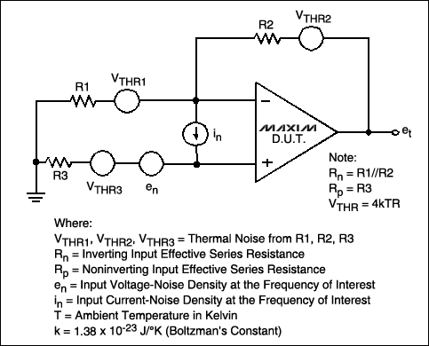
This article examines key parameters in choosing a low noise amplifier for low frequency analog applications such as buffering data converters, amplifying strain-gauge signals, and pre-amplifying microphone outputs. Low noise amplifiers (LNAs) are critical components in various analog applications that...

This 555 timer circuit temperature monitoring system project can monitor temperature at up to four points. The system allows for the selection of whether the alarm should be triggered when the temperature increases or decreases, depending on the resistance...
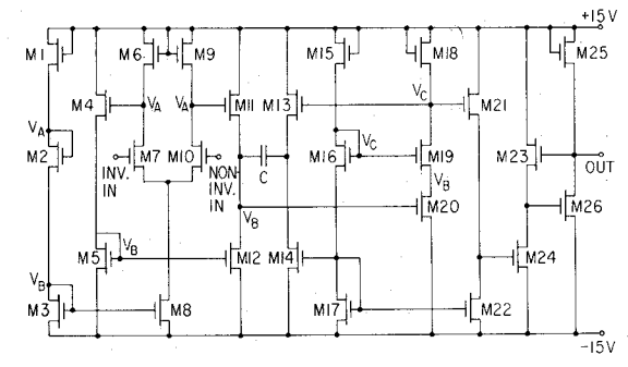
An internally compensated operational amplifier has been fabricated using n-channel Al-gate MOS technology, utilizing only enhancement mode devices. The circuit is designed to ensure that its performance remains insensitive to process parameters. The input stage consists of a source-coupled...
Warning: include(partials/cookie-banner.php): Failed to open stream: Permission denied in /var/www/html/nextgr/view-circuit.php on line 713
Warning: include(): Failed opening 'partials/cookie-banner.php' for inclusion (include_path='.:/usr/share/php') in /var/www/html/nextgr/view-circuit.php on line 713