
High Efficiency LT3463A Dual Micropower DC/DC Converters Block Diagram and Datasheet
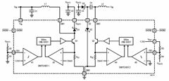
The LT3463A is a highly efficient, dual micropower DC/DC converter designed for applications requiring low output current while maintaining a compact footprint. The device employs a constant off-time control method, which enhances its efficiency across a broad spectrum of output currents. This feature is particularly beneficial in battery-powered systems where energy conservation is paramount.
The internal Schottky diodes integrated within the LT3463A help minimize voltage drop and switching losses, further contributing to overall efficiency. The circuit typically operates in a step-up (boost) configuration, allowing the converter to generate a higher output voltage from a lower input voltage source. This is crucial in applications such as portable devices, where battery voltage can be low and needs to be elevated to power various components.
The circuit diagram illustrates the essential components and their interconnections, including input and output capacitors, inductors, and feedback resistors, which are critical for establishing the desired output voltage and current levels. The feedback loop ensures that the output voltage remains stable despite variations in load conditions and input voltage.
In summary, the LT3463A dual micropower DC/DC converters with constant off-time control and internal Schottky diodes represent a robust solution for efficient voltage conversion in low-power applications, providing reliability and performance in a compact design.A constant off-time control which provide a high efficiency over a wide range of output current can be used by the LT3463A dual micropower DC/DC converters with internal Schottky Diodes, as described in the following circuit diagram and the datasheet 🔗 External reference
Related Circuits
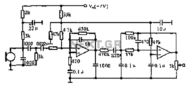
The CX9800 models of mobile phones and desktop PCs feature a high-performance voice processing circuit that compresses the amplitude and bandwidth of the microphone signal. This design enhances the sensitivity of the microphone and its adaptability to varying distances....
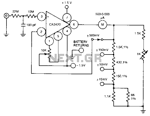
A resistance of 1,000,000 MΩ takes advantage of the high input impedance of the CA3420 BiMOS op-amp. Only two 1.5-V AA-type penlite batteries are required for use. Full-scale deflection is ±500 nV, ±150 mV, and ±15 mV. The circuit utilizes...
Power line fluctuations and cut-offs can damage electrical appliances connected to the line, particularly domestic appliances such as refrigerators and air conditioners. Operating a refrigerator on low voltage can lead to excessive current flowing through the motor, resulting in...
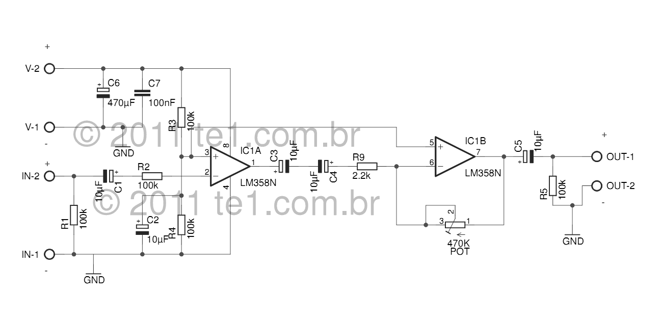
The LM358 series consists of two independent, high-gain, internally frequency-compensated operational amplifiers designed specifically to operate from a single power supply over a wide range of voltages. Operation from split power supplies is also possible, and the low power...
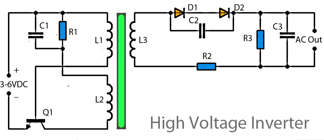
This inverter circuit operates using a transistor and transformer, along with other components, to elevate the voltage. The input supply voltage ranges from 3V to 6V DC, which is then converted to a high voltage AC output. However, the...
This page presents a replacement circuit for the LM3909 LED Flasher/Oscillator utilizing discrete components. The circuit functions similarly to the integrated LM3909 but features minor variations in the component values used. Although the LM3909 is still available, it tends...