
High frequency crystal oscillator
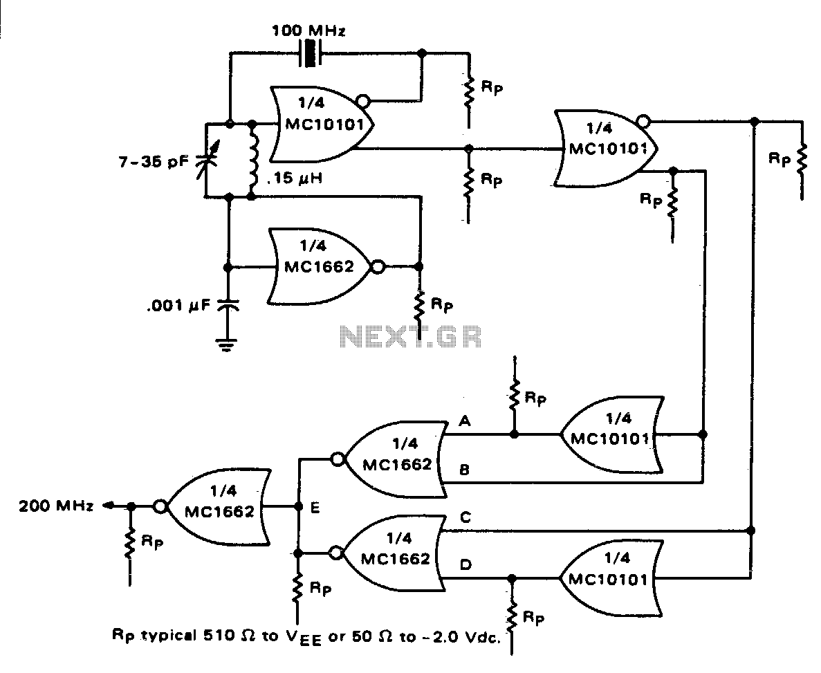
The MC10101 integrated circuit is a versatile component often used in high-frequency applications. In this configuration, it operates as a crystal oscillator, generating a stable frequency output at 100 MHz. The crystal oscillator's feedback loop is critical for maintaining oscillation stability and precision. The inclusion of an LC tank circuit allows for fine-tuning of the oscillator's frequency, ensuring that it aligns perfectly with the desired 100 MHz output.
The buffering section of the MC10101 is essential for isolating the oscillator from subsequent circuitry, preventing loading effects that could alter the oscillation characteristics. This section provides two complementary outputs, which are particularly useful in digital applications where both high and low logic levels are needed simultaneously.
In the frequency doubler configuration, the use of phase shifters is vital for generating the necessary timing relationships between the signals. The two MC10101 gates act as phase shifters, ensuring that the output signals are appropriately delayed to achieve the desired 90° phase difference. This phase shift is crucial for maintaining a 50% duty cycle, which is often required in digital signal applications to ensure proper timing and synchronization.
The additional use of MC1662 NOR gates in this circuit aids in further processing the signals, allowing for the generation of a doubled frequency output while maintaining signal integrity. The design can also accommodate variations in output frequency through the use of delay lines, which can provide precise timing adjustments for applications operating at higher frequencies, such as 200 MHz.
Overall, this circuit configuration showcases the capabilities of the MC10101 and MC1662 components in high-frequency signal generation and manipulation, making it suitable for a wide range of electronic applications that demand precision and reliability.One section of the MC10101 is connected as a 100 MHz crystal oscillator with the crystal in series with the feedback loop. The LC tank circuit tunes the 100 MHz harmonic of the crystal and may be used to calibrate the circuit to the exact frequency.
A second section of the MC10101 buffers the crystal oscillator and gives complementary 100 MHz signals. The frequency doubler consists of two MC10101 gates as phase shifters and two MC1662 NOR gates For a 50% duty cycie at the output, the delay to the true and complement 100 MHz signals should be 90°. This may be built precisely with 2 ns delay lines for the 200 MHz output or approximated by the two MC10101 gates as shown.
🔗 External reference
Related Circuits
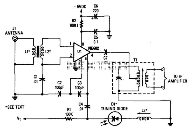
In this configuration, the NE602 serves as a frequency converter in a superheterodyne front-end setup. L1 and L2 form a broadband toroidal transformer, although a tuned transformer may also be utilized. The supply voltage ranges from +5 to +9...
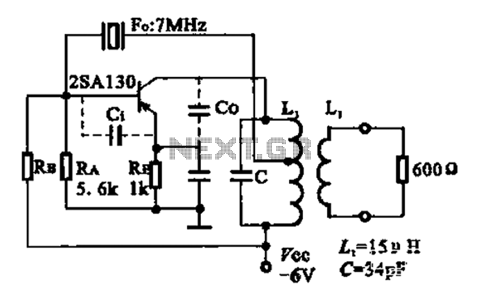
The 2SA130 transistor is used in an oscillator circuit with an oscillation frequency of 7 MHz. The power supply voltage is 6V, and the load is a frequency-selective resonant circuit with a quality factor of 600. The circuit utilizes the...
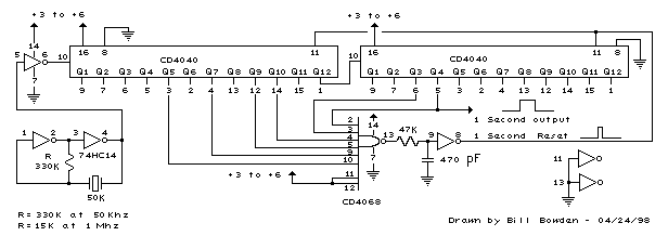
The schematic below illustrates the division of a crystal oscillator signal by the crystal frequency to obtain an accurate 1-second time base with a precision of 0.01%. Two cascaded 12-stage counters (CD4040) form a 24-stage binary counter, and the...
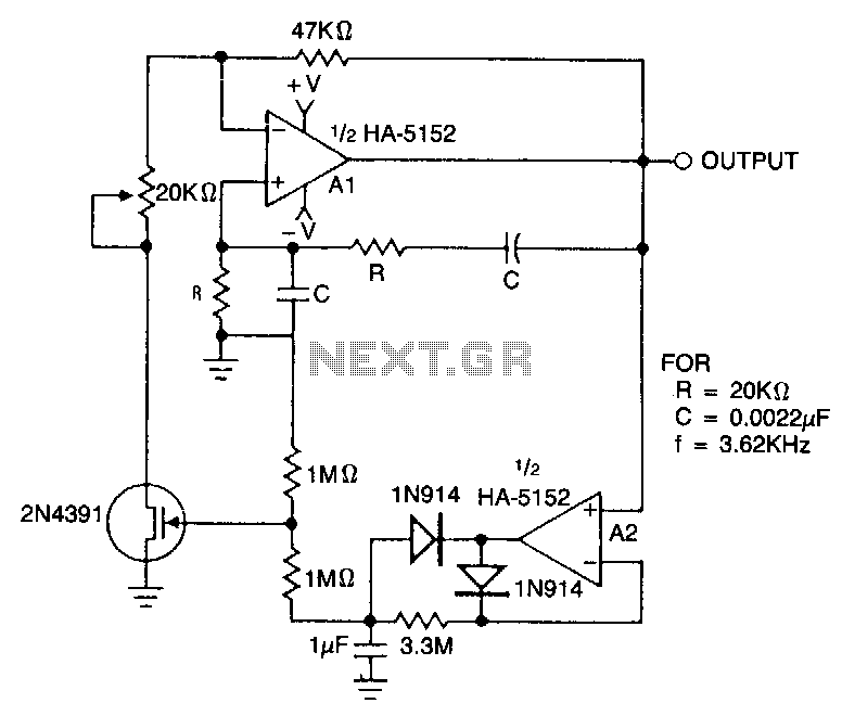
This circuit employs an HA-5152 dual operational amplifier and a field-effect transistor (FET) to create a low-voltage, low-power Wien bridge sine-wave oscillator. The frequency of oscillation is controlled by resistors and capacitors, while the FET functions as a voltage-controlled...
The concept for this crystal tester circuit originated from the necessity to evaluate a large quantity of oscillator crystals that were not in use within a hobby box. Testing each crystal individually without the proper equipment would have been...
The overall performance of any RF circuit regarding its phase noise and spectral purity depends significantly on the frequency-generating circuitry, commonly an oscillator. Low noise oscillators with high spectral purity are neither mysterious nor magical. Many individuals perceive the...
Warning: include(partials/cookie-banner.php): Failed to open stream: Permission denied in /var/www/html/nextgr/view-circuit.php on line 713
Warning: include(): Failed opening 'partials/cookie-banner.php' for inclusion (include_path='.:/usr/share/php') in /var/www/html/nextgr/view-circuit.php on line 713