
Receiver Frequency-Converter Stage
The NE602 integrated circuit is a widely used component in radio frequency applications, particularly in superheterodyne receivers. This specific circuit configuration highlights its role as a frequency converter, allowing for efficient signal processing. The use of a broadband toroidal transformer (L1 and L2) is advantageous for maintaining a wide bandwidth, which is essential in applications that require the reception of signals over a broad frequency range, from audio frequencies up to 30 MHz.
The choice of supply voltage between +5 to +9 VDC provides flexibility in power requirements, accommodating various design constraints and power supply options. The tuning of T1 to the IF frequency of 455 kHz is a standard practice in superheterodyne designs, ensuring that the incoming RF signals are mixed down to a lower frequency that is easier to process.
The circuit's adaptability is further enhanced by the option to replace the varactor tuning diode with an air-variable capacitor. This substitution can be beneficial in applications where fine-tuning of the frequency is necessary or where the characteristics of the varactor diode may not meet specific performance criteria.
The turns ratio of the transformer (1:12) indicates that the primary winding has 1 turn for every 12 turns on the secondary, which is a common configuration in RF transformers to step up the voltage while maintaining impedance matching. The resonance of L3 with the capacitance of diode D1 is critical for achieving the desired local oscillator frequency, which is pivotal in determining the operational parameters of the receiver.
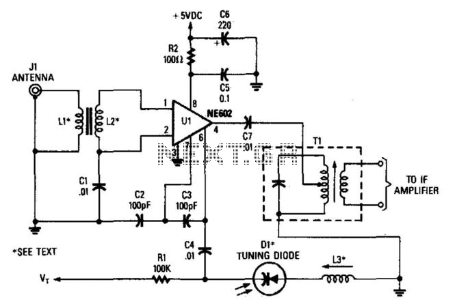
In summary, this circuit design effectively utilizes the NE602 and associated components to create a versatile and efficient frequency conversion stage in a superheterodyne receiver, capable of handling a wide range of frequencies while providing options for tuning and component substitution. In this case, the NE602 is used in this superhet front-end configuration. Ul serves as a frequency conve rter. L1/L2 is a broadband toroidal transformer. A tuned transformer may be used instead. The supply voltage is + 5 to +9 Vdc. Tl is tuned to the IF frequency. The typical IF frequency is 455 kHz. This circuit, depending on Ll, L2, and L3, should be usable in the frequency range from audio to 30 MHz. The varactor tuning diode can be replaced with an air-variable capacitor, if desired. Ll, L2 1:12 Turns Ratio Toroid (Broadband). L3 Resonates to L.O. Frequency with Dl capacitance. LO FREQ Desired received frequency ± IF frequency. 🔗 External reference
Related Circuits
The TDA7000 is a well-known FM radio receiver integrated circuit (IC), also referred to as a one-chip FM radio receiver. It operates within the VHF FM band, covering frequencies from 70 to 120 MHz. Introduced in the 1980s, the...
This schematic illustrates a high-quality AM radio receiver circuit centered around the MK484 AM radio integrated circuit (IC). The MK484 is known for its high sensitivity and superior performance, featuring only three leads and housed in a TO-92 package....
The original data sheet for the MK414 indicates that the maximum working frequency is approximately 4 MHz. SW transmissions are sufficiently strong that this receiver can effectively operate with signals up to about 6 or 7 MHz. A 10k...
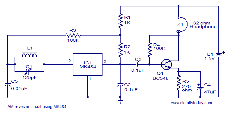
A cost-effective and straightforward AM receiver circuit utilizing the MK484 integrated circuit. The circuit requires minimal external components and operates within a frequency range of 150 kHz to 3 MHz. The MK484 AM receiver circuit is designed for simplicity and...
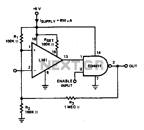
The trip point is set halfway between the supplies by R1 and R2; R3 provides over 200 mV of hysteresis to increase noise immunity. The maximum frequency of operation is about 300 kHz. If response to TTL levels is...
This circuit resembles an LED clock, utilizing 12 neon indicator lamps in place of LEDs. It operates on two high-capacity nickel-cadmium (Ni-Cad) cells providing 2.5 volts, allowing sustained operation for several weeks. The high voltage (70 volts) required for...