
High Frequency Switch
The high-frequency switch circuit designed with the 2N4391 transistor is engineered for applications requiring rapid switching and minimal signal distortion. The 2N4391 is a JFET (Junction Field Effect Transistor) known for its low noise and high-speed operation, making it suitable for RF (Radio Frequency) applications.
In the off state, the circuit achieves a high off-impedance of less than 0.2 pF, which is crucial for maintaining signal integrity by preventing unwanted loading of the preceding stage. This characteristic ensures that the circuit can effectively isolate different parts of a system when the switch is not engaged.
When the switch is activated (in the on state), the circuit demonstrates a low on-resistance, which minimizes voltage drop and power loss across the switch. This feature is particularly important in high-frequency applications, where maintaining the amplitude and phase of the signal is critical.
The overall design may include biasing resistors to set the operating point of the 2N4391, ensuring that it operates within its optimal range. Additionally, decoupling capacitors might be employed to filter out high-frequency noise, further enhancing the performance of the circuit.
In summary, this high-frequency switch circuit utilizing the 2N4391 is characterized by its high off-impedance and low on-resistance, making it an effective solution for applications requiring reliable and efficient switching at high frequencies.This is high frequency switch circuit. This circuit uses the 2N4391. When it is off, it will provide a high off-impedance (<0.2pF) and low on-resistance of.. 🔗 External reference
Related Circuits
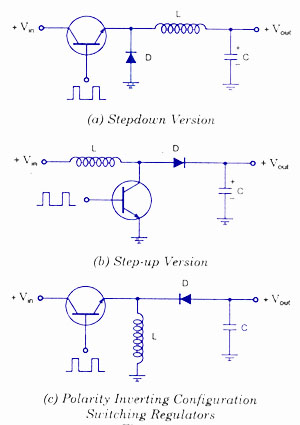
Switching voltage regulators include step-up, step-down, and polarity-inverting configurations, along with their working principles and circuit diagrams. Switching voltage regulators are essential components in modern electronic circuits, providing efficient voltage conversion. These regulators can be categorized into three main types:...
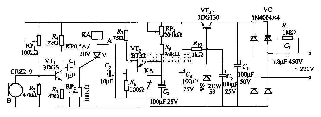
The circuit features voice switches with Figure 2109. It utilizes a single-junction transistor (VT2) and RC components to create a delay. The delay time can be adjusted using the potentiometer (RP3) or the capacitor (C3). The described circuit employs a...
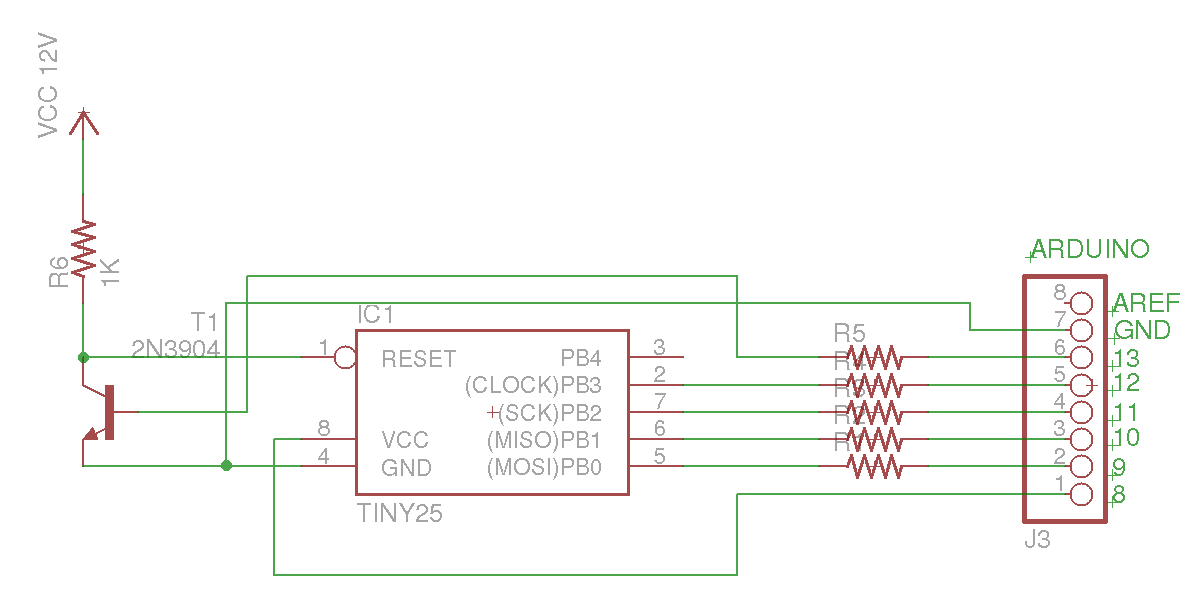
This Arduino sketch is designed to recover ATtiny microcontrollers that have become non-functional due to incorrect fuse settings. It achieves this by placing the affected ATtiny into high-voltage serial programming mode and rewriting the fuses to safe values. The...
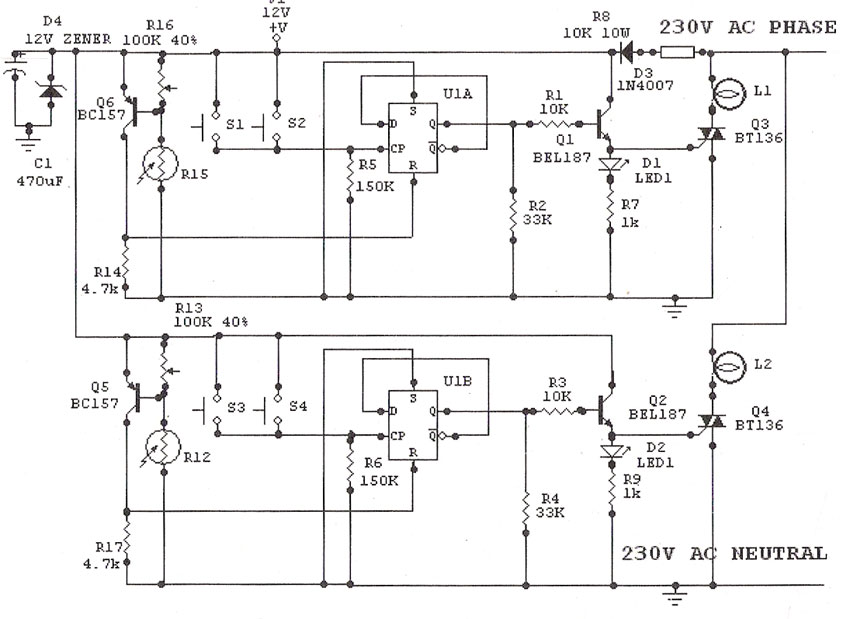
Light Sensitive Staircase Switch with Triac. The operation of the third circuit is similar, except that it incorporates photo sensitivity. The circuit is illustrated in the schematic. When there is insufficient light... A light-sensitive staircase switch utilizing a TRIAC is...
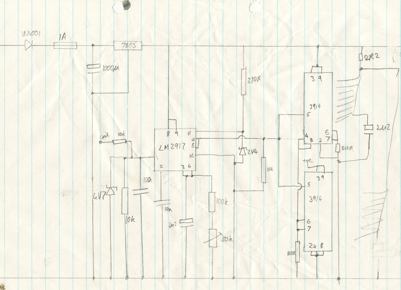
This circuit utilizes an LM2917 frequency-to-voltage converter. The input is connected to the low voltage side of the ignition coil, with various components designed to produce a full-scale output at 6000 RPM, corresponding to 12000 ignition pulses per minute,...

The receiver section was not illustrated as it is considered standard. The TRIAC switch section depicted below can be controlled using standard 4000 series CMOS logic. The TRIAC switch section operates by utilizing a TRIAC (Triode for Alternating Current) component,...
Warning: include(partials/cookie-banner.php): Failed to open stream: Permission denied in /var/www/html/nextgr/view-circuit.php on line 713
Warning: include(): Failed opening 'partials/cookie-banner.php' for inclusion (include_path='.:/usr/share/php') in /var/www/html/nextgr/view-circuit.php on line 713