
Rc 3 way Light Switch

The TRIAC switch section operates by utilizing a TRIAC (Triode for Alternating Current) component, which is a semiconductor device that can control power flow in AC circuits. The 4000 series CMOS (Complementary Metal-Oxide-Semiconductor) logic family provides the necessary control signals to trigger the TRIAC.
In a typical configuration, the TRIAC is connected in series with the load (e.g., a lamp or motor), and it is triggered into conduction when a gate pulse is applied. The gate pulse can be generated by the CMOS logic gates, which may include NOT, AND, OR, or NAND gates, depending on the desired control logic for the application.
The input to the CMOS logic can be derived from various sensors or switches, allowing for flexible control schemes. For example, a simple button press can trigger a logic high, which then activates the corresponding gate in the CMOS logic to send a pulse to the TRIAC gate.
The use of 4000 series CMOS logic is advantageous due to its low power consumption and compatibility with a wide range of input voltages, making it suitable for battery-operated devices or low-power applications. Additionally, the TRIAC allows for efficient control of AC loads, enabling features such as dimming lights or controlling the speed of motors.
It is essential to include protective components, such as snubber circuits, to prevent voltage spikes from damaging the TRIAC or the CMOS logic. Proper heat dissipation measures should also be implemented to ensure reliable operation of the TRIAC under load conditions.
Overall, the integration of a TRIAC with 4000 series CMOS logic provides a robust solution for controlling AC loads in various electronic applications.Did not bother to draw out the receiver section because it is quite ordinary. The TRIAC switch section shown below can be controlled by ordinary 4000 series CMOS logic. 🔗 External reference
Related Circuits
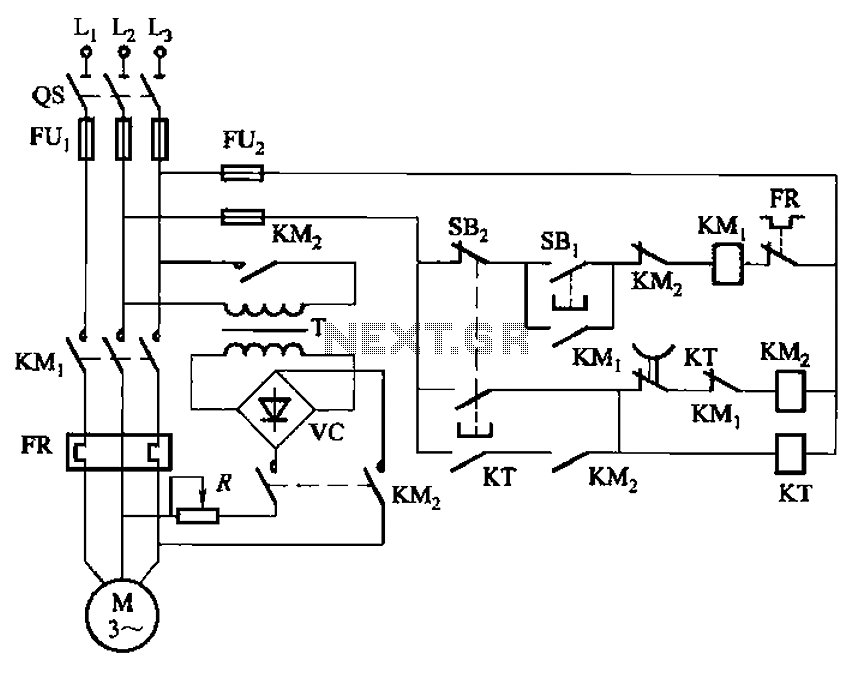
The circuit depicted in Figure 3-135 employs a time relay (KT) to determine the braking time. The circuit utilizes a time relay, which is a crucial component for controlling the duration of the braking process. The time relay KT is...
Dimmer Switch - Dimmer Switch Working, Installation, Circuits and Explanation. A dimmer switch is a device that allows for the adjustment of the brightness of a light fixture. It operates by varying the voltage and current supplied to the light...
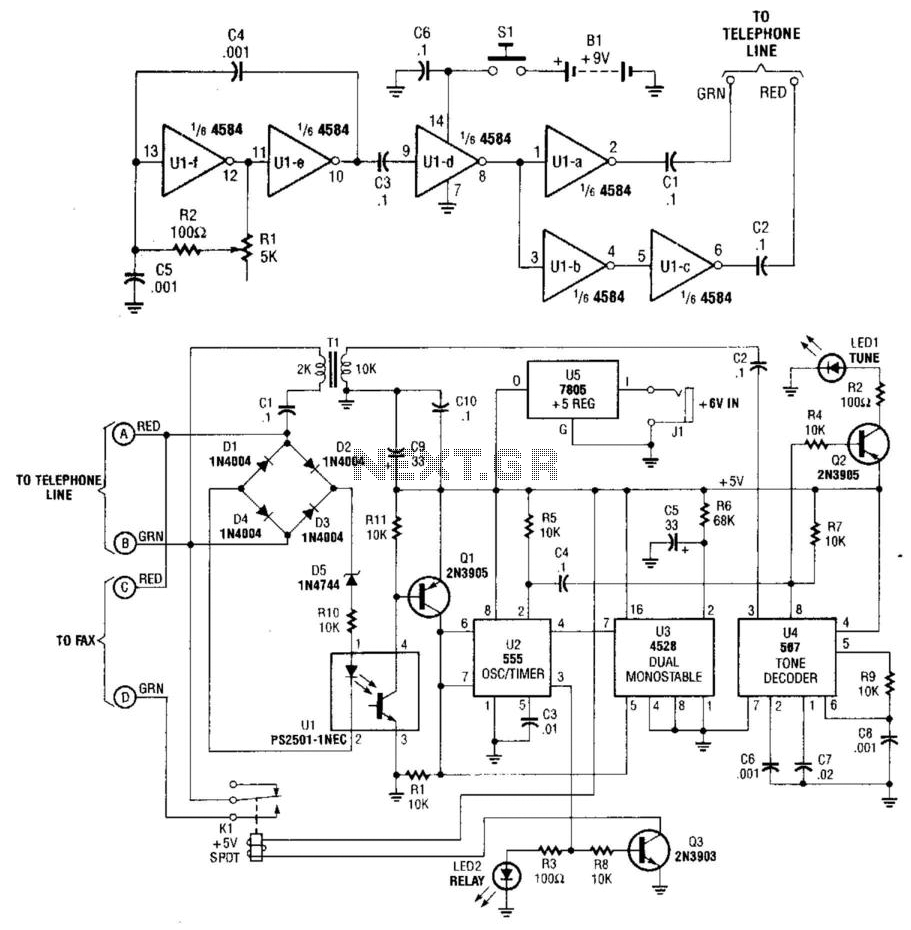
This system uses a transmitter operating at approximately 100 kHz to control a remote receiver. A line splitter can connect the transmitter to the active telephone line. The transmitter is a CMOS oscillator equipped with output buffer stages to...
The game was originally designed to position three balls locked in holes on a slowly rotating ring around the Deadworld. Once the third ball was secured, a mechanical arm would release them, dropping the balls onto the playfield. This...
The SFH505A, manufactured by Siemens, integrates an infrared diode receiver, amplifier, demodulator, and a band-pass filter to minimize interferences. This circuit operates effectively in various applications. The SFH505A is a versatile optical receiver module designed for infrared communication systems. It...
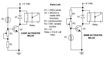
The potentiometer adjusts the trigger level. The diode in the circuit diagram is specified as 1N914, which is suitable for light-duty relays; however, since the 1N914 is a signal diode, it is not ideal for this application. A 1N4001...