
Switching Voltage Regulators-Step up Step down and polarity invert
Switching voltage regulators are essential components in modern electronic circuits, providing efficient voltage conversion. These regulators can be categorized into three main types: step-up (boost), step-down (buck), and polarity-inverting configurations.
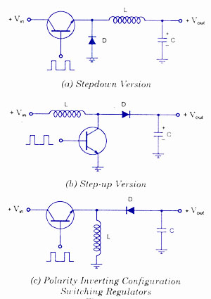
A step-up voltage regulator increases the input voltage to a higher output voltage. This is achieved using an inductor, switch (typically a transistor), diode, and capacitor. During the on-phase, the switch closes, allowing current to flow through the inductor, which stores energy. When the switch opens, the energy stored in the inductor is released, resulting in a higher output voltage across the load due to the inductor's tendency to maintain current flow.
Conversely, a step-down voltage regulator reduces the input voltage to a lower output voltage. This configuration also employs an inductor, switch, diode, and capacitor. When the switch is closed, the inductor stores energy. When the switch opens, the inductor discharges its energy through the load, resulting in a lower output voltage. The control mechanism in both step-up and step-down regulators is typically managed by a pulse-width modulation (PWM) technique, which adjusts the duty cycle of the switch to maintain the desired output voltage.
Polarity-inverting voltage regulators provide a negative output voltage relative to the input. This configuration utilizes a similar approach as the step-up and step-down regulators but includes additional components to invert the output. The circuit typically includes an inductor and a switch, which operates in a manner that allows the inductor to discharge in the opposite polarity when the switch is turned off.
Circuit diagrams for these configurations illustrate the interconnections between components, showcasing how energy flows through the system. Each type of regulator has its specific applications, including power supply units, battery chargers, and various electronic devices requiring stable voltage levels. Understanding the principles and design of these switching voltage regulators is crucial for optimizing performance and efficiency in electronic circuits.Switching Voltage Regulators-Step up, Step down, and polarity inverting configuration, working, and circuit diagram.. 🔗 External reference
Related Circuits
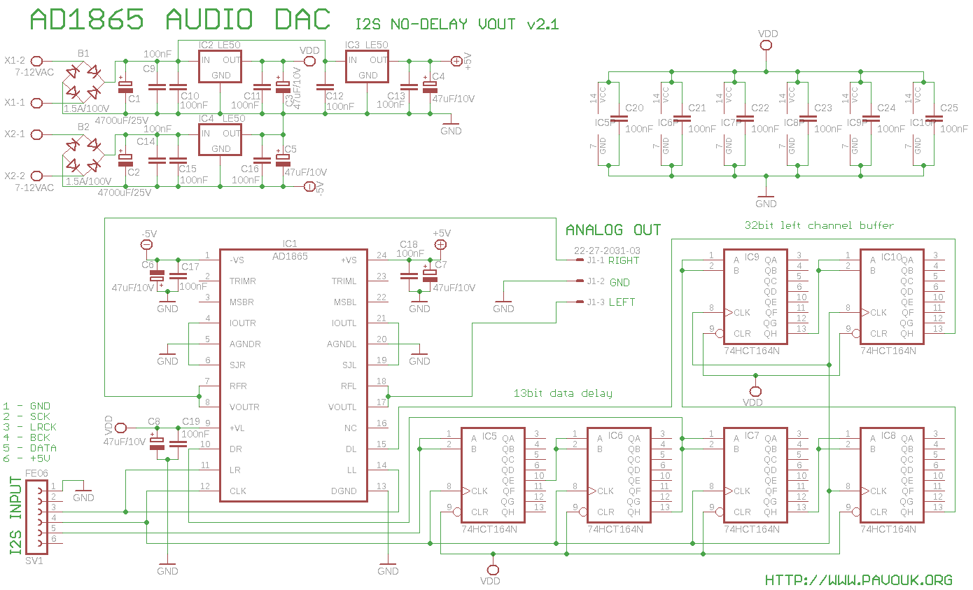
The AD1865 circuit is regarded as one of the best 18-bit stereo audio DACs available. Previous DAC designs encountered issues with weak current output, leading to the decision to utilize the integrated current-to-voltage (I/V) converter instead of an external...
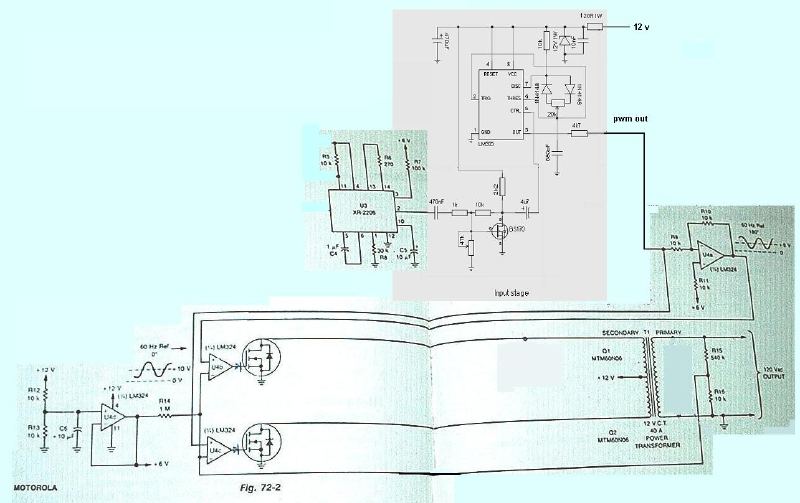
A few months ago, a search was conducted for an easy-to-build PWM inverter that does not require any PIC programming. The investigation led to a consideration of a 555 PWM amplifier circuit. The 555 timer IC is widely used in...
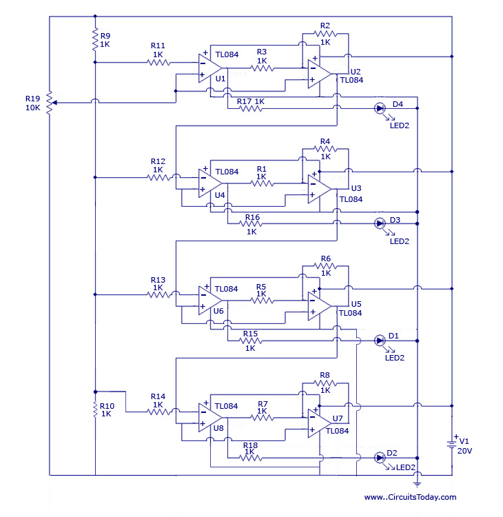
The design originated from the interest in discovering a new technique for analog to digital conversion. The two types of ADC (Analog to Digital Converter) that influenced the development of this circuit are the Flash Type ADC and the...
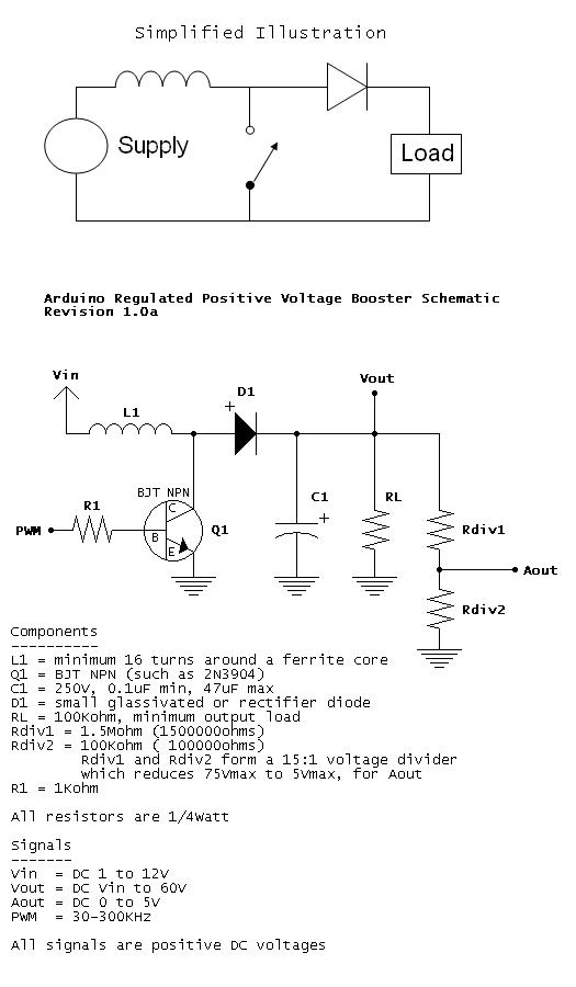
When Q1 is active, a larger current begins to flow through L1 to ground. When Q1 is switched off, the current through L1 tries to remain constant, resulting in an increased voltage. By varying the PWM duty cycle, the...
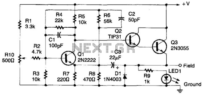
This regulator circuit can be used on an alternator that has one field terminal grounded. When the input voltage becomes too high, Q1 conducts, and the base of Q2 is driven toward ground, reducing the voltage fed to Q3....

This voltage booster circuit for driving one or more white LEDs utilizes a 555 timer as its main component. The timer, designated as IC1, operates as a resettable astable multivibrator with R1, R2, and C2 serving as the timing...