
High Input Voltage regulator using LM340
The high input voltage regulator circuit utilizes an LM340 voltage regulator to maintain a stable output voltage of 5V. The LM340 is designed to operate within specific input voltage limits as detailed in its datasheet. Exceeding these limits can lead to catastrophic failure modes, particularly affecting the transistor Q1, which is crucial for regulating the output voltage.
In the event of an output short circuit, the collector-emitter voltage of Q1 can reach levels that exceed its maximum ratings, leading to thermal runaway and eventual failure. Additionally, if the output is not grounded, the same issue can occur due to excessive voltage stress on the transistor. To mitigate these risks, the circuit incorporates a zener diode, which is connected in series with the input voltage. This configuration effectively clamps the input voltage to a safe level, ensuring that the LM340 operates within its specified limits.
The zener diode serves as a protective element, allowing the circuit to tolerate higher input voltages without compromising the integrity of the regulator. By selecting an appropriate zener voltage, the input can be level-shifted to maintain the necessary voltage for proper operation of the LM340.
The schematic of the circuit would typically include the LM340, the zener diode, and associated passive components such as resistors and capacitors to ensure stability and performance. Capacitors may be included at the output to filter any ripple and maintain a steady voltage output, while additional components may be used to enhance transient response and overall efficiency. Proper layout and thermal management are also critical in the design to prevent overheating and ensure reliable operation over a range of environmental conditions.This circuit is the High Input Voltage regulators, which generate voltage 5V. In these circuit LM340 input voltage must remain within the limits specified in the data sheet. If the device is operated above the absolute maximum input voltage rating, two failure modes can occur. With the output shorted to ground, or, even with the output is not grou nded, the transistor Q1 may fail because it is operated with the collector-emitter voltage of about 4. 0V below the input. If the supply is available only running at a higher voltage than the specified maximum, one of the simplest ways to protect the regulator is to connect the zener diode in series with input from the device to level shift the input voltage.
Here is a schematic drawing: 🔗 External reference
Related Circuits
This device is a successor to the PIC16C71 4-digit LED frequency counter and voltmeter. It omits some hard-to-find components from the previous version that have been out of production for some time. The earlier PIC16C71 has been replaced with...
It is a voltage regulator that allows a 6v portable supply to be derived from the 12v car battery. You can add a 6.2V zener diode and a LED to warn you when the input supply is overvoltage. If...
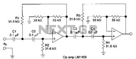
This circuit, which utilizes an LM1458 or a similar operational amplifier, functions as a fourth-order high-pass filter with a roll-off rate of 24 dB per octave. The resistor values Rx/R2 and RJRV can be adjusted to accommodate different cutoff...
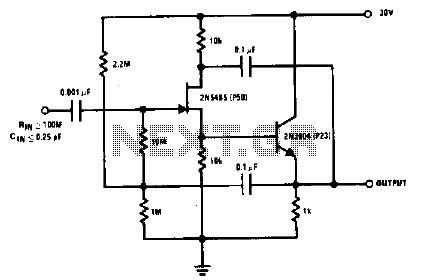
The 2N5485, which has a very low-capacity legacy, is always operated as a source follower with gate bias bootstrap. In this circuit, nothing is left to chance in reducing input capacitance. The 2N5485 is a JFET (Junction Field Effect Transistor)...
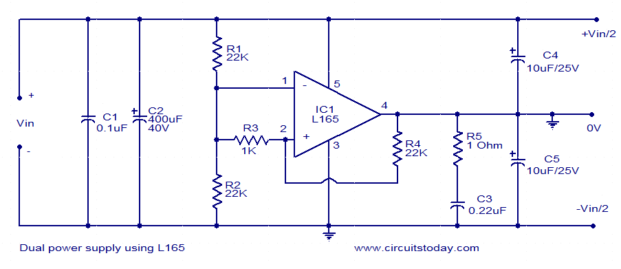
This dual power supply utilizes the L165 power operational amplifier from SGS-Thomson Microelectronics. The L165 IC can deliver up to 3.5A of current, with internal current limiting. It is available in a Pentawatt package, making it well-suited for power...
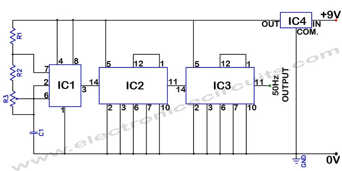
Accurate 50Hz Oscillator Circuit Using 555 and 7490. This circuit generates a 50Hz pulse. It consists of a 555 timer and two 7490 divide-by-ten counters. The circuit utilizes a 555 timer configured in astable mode to produce a square wave...