
Dual power supply using L165
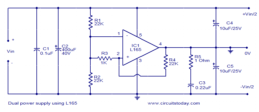
The dual power supply circuit based on the L165 operational amplifier is designed to provide a stable dual output voltage, which is essential for various electronic applications. The operational amplifier is configured to function as a voltage amplifier, where the output voltage is derived from the input voltage through a specific resistor network. The resistors R1 and R2 form a voltage divider, determining the gain of the amplifier circuit.
The input voltage (Vin) is supplied to the circuit, and the output is generated as a symmetrical dual voltage, typically +12V and -12V for a 24V input. This configuration is particularly beneficial for powering op-amps and other analog devices that require dual polarity supplies.
Capacitor C1 plays a crucial role in decoupling, ensuring that high-frequency noise does not affect the operational amplifier's performance. It provides a low-impedance path to ground for high-frequency signals, effectively stabilizing the power supply. Capacitor C2, as the input filter capacitor, smooths out any ripples or fluctuations in the input voltage, providing a more stable voltage to the L165.
To improve the output voltage symmetry, capacitors C4 and C5 are strategically placed in the circuit. These capacitors help to balance the output characteristics, ensuring that both the positive and negative outputs remain equal and stable under varying load conditions. This is critical for applications requiring precise voltage levels, such as audio equipment, instrumentation, and analog signal processing.
Overall, this dual power supply circuit exemplifies a robust design using the L165 operational amplifier, providing reliable performance for a variety of electronic applications.This dual power supply is based on the L165 power operational amplifier from SGS-Thomson Micro electronics. The IC L165 can easily deliver up to 3. 5A of current (internally limited). The IC is available in Pentawatt package and is very suitable for power supply applications like this.
Here the L165 is wired as a voltage amplifier which amplifies t he voltage available at the junction between R1 and R2. The output voltage will be always half of the input voltage (Vin). For example if you give 24V at the input (Vin), you will get a +12V/-12 V at the output. C2 is the input filter capacitor and C1 is the input decoupling capacitor. C4 and C5 and meant for improving the symmetry of the output voltage. 🔗 External reference
Related Circuits
The circuit comprises an N-MOSFET voltage follower (T1, common drain) and a current source (T2, NPN Darlington). The current source is set to 2.2 Amps. With a supply voltage of 40V, the circuit can deliver approximately 17W into an...
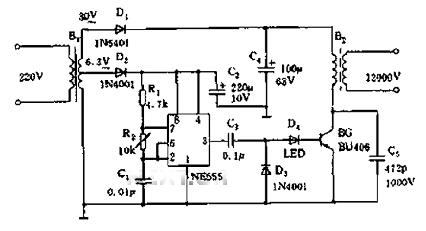
The neon voltage power supply circuit is straightforward to construct, offering stable output power and other desirable characteristics. The core component of this circuit is the NE555 timer, which generates a high-frequency oscillation signal in the range of 15...
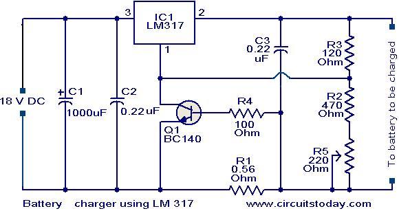
This is a simple yet effective battery charger circuit utilizing the LM317 integrated circuit (IC). The circuit is designed for charging 12V lead-acid batteries and can be easily assembled on a general-purpose printed circuit board (PCB). The core component...
Iron the printed layout at a low heat setting until the ink adheres to the PCB. This process may take over an hour to complete. Afterward, remove the transparent paper. Next, submerge the PCB in Ferric Chloride solution until...
A pulse width modulator generates a PWM signal, which consists of pulses with a constant frequency while the duty cycle varies according to a modulating signal. A pulse width modulator (PWM) is an essential component in various electronic applications, particularly...
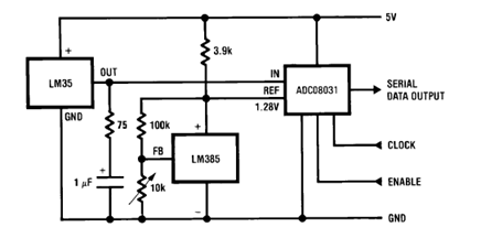
The circuit illustrates a Temperature to Digital Converter diagram utilizing the LM35 sensor, which includes a beneficial bypass capacitor connected from VIN to ground and a series RC damper. The described circuit employs the LM35 temperature sensor, a precision integrated...