
high performance sawtooth generator

The sawtooth generator circuit described operates by utilizing a combination of active and passive components to produce a linear ramp waveform. The core of the circuit consists of an operational amplifier (IC1) configured as a voltage-controlled current source, which is essential for controlling the charging and discharging cycles of capacitor C1. The resistor R1 plays a crucial role in setting the charging current, while Q1, as part of the current source, ensures that the output remains stable and responsive to voltage changes.
During operation, capacitor C1 discharges through the current Io until its voltage falls below the threshold of 1.66V. This triggers a transition in the output of the comparator IC2A from a low state to a high state (5V), initiating the charging phase of C1. The charging process is governed by the diode-connected transistor Q2, which allows current to flow into C1, thereby increasing its voltage until it reaches 3.33V. At this point, the comparator IC2A detects the voltage level and switches its output back to a low state (ground), completing one cycle of the sawtooth waveform.
The frequency of the output waveform is directly influenced by the values of C1 and R1. By adjusting these components, the designer can manipulate the timing characteristics of the circuit, allowing for a wide range of frequencies to be generated. However, it is important to consider the limitations imposed by the slew rate and settling time of the comparator IC2A, as these factors can affect the linearity and stability of the output waveform.
In summary, this sawtooth generator circuit is a cost-effective solution for generating a sawtooth waveform and an auxiliary square wave. Its design allows for frequency modulation, making it suitable for applications where frequency sweeping is required. The careful selection of components and their values is critical for achieving the desired performance and operational range of the generator.This is a design for sawtooth generator circuit. The advantage of this circuit is low cost and produces an auxiliary square wave at the same frequency. This circuit can be used to sweep the frequency of another generator. This is the figure of the circuit. A voltage-controlled current source is formed by IC1 with R1 and Q1. The C1 is discharged by current Io until it`s voltage is less than 1. 66V. It will swing its output to 5V and trips the IC2A comparator. The C1 is charged by current through the diode-connected transistor (Q2) until its voltage reaches 3. 33V, so the IC2A output to swing back to ground. The output frequency is determined by : We can set the fOUT as high as desired by adjusting the values of C1and R1, subject to the limitations of comparator IC2A`s slew settling and rate time.
The frequency range over which it can operate determined by generator`s linearity. 🔗 External reference
Related Circuits
This is a basic 555 square wave oscillator designed to generate a 1 kHz tone for an 8-ohm speaker. In the circuit, the speaker is isolated from the oscillator by an NPN medium power transistor, which supplies more current...
The SP6691 circuit is designed to provide a high output voltage using a lower voltage boost regulator by incorporating a charge pump circuit. This configuration can convert a standard 30V boost regulator into a 60V boost regulator if necessary....

Sometimes referred to as the JFET µ-amp, this circuit offers a very low power, high gain amplification function. As the drain current decreases, the µ of a JFET increases, meaning that the lower the drain current, the greater the...

Yesterday, no enhancements were made to the circuit on the blog. Today, a high current power supply capable of delivering 10A has been introduced, featuring an adjustable voltage or variable voltage regulator that can operate within a range of...
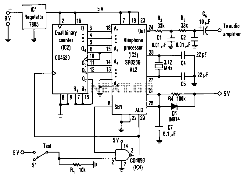
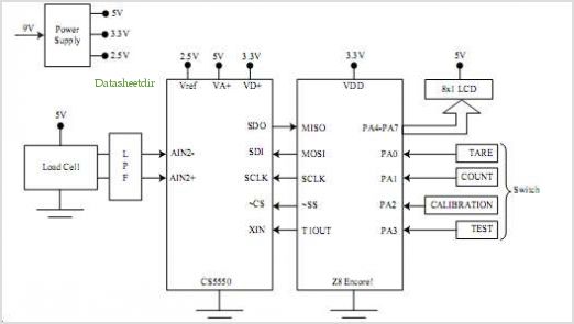
The circuit is a general-purpose system with various applications that vocalizes 59 allophones stored in the speech processor. After filtering and amplification, its pulse-code-modulated output can drive an 8-ohm speaker. The address pins of the processor, labeled A1 to...
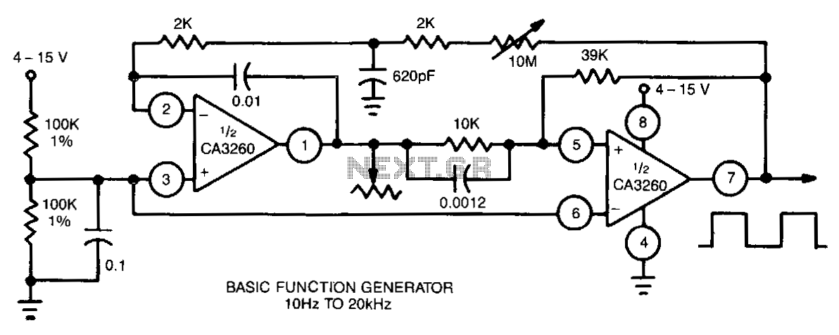
This function generator utilizes a CA3260 BiMOS operational amplifier to perform both integrator and switching functions. A 620-pF capacitor and a 2-kΩ resistor are employed to shape the feedback square wave, minimizing spikes. The device covers the full audio...