
High Resolution Digital Weigh-scale Design Using Z8 Encore! ?® Microcontrollers

The SP6691 circuit leverages a combination of a boost regulator and a charge pump to achieve high output voltage levels efficiently. The boost regulator operates by increasing the input voltage to a higher output voltage, while the charge pump enhances this capability by utilizing capacitive charge storage and transfer techniques. When configured as a 60V boost regulator, the circuit effectively doubles the output voltage from a standard 30V input, making it suitable for applications requiring higher voltage levels without the need for a more complex and expensive power supply solution.
The testing conducted at 43V output voltage demonstrates the circuit's reliability and performance under operational conditions. The design includes careful selection of components to ensure that the output voltage remains stable and within specified limits. Capacitor C3 plays a crucial role in this configuration, as it stabilizes the output voltage by maintaining a voltage that is roughly half of VOUT, which can help in reducing stress on the circuit and improving overall efficiency.
The application schematic provided in the report outlines the connections and layout of the circuit components, facilitating easier implementation and troubleshooting. The Bill of Materials (BOM) lists all components necessary for constructing the circuit, ensuring that all parts are readily available for assembly. Figures 1 through 7 illustrate various aspects of the circuit’s electrical performance, including voltage regulation, output stability, and efficiency metrics, providing a comprehensive overview of the design's capabilities. This detailed documentation serves as a valuable resource for engineers and developers looking to implement or modify the SP6691 circuit in their applications.This circuit SP6691 has been designed to provide a high output voltage with a lower voltage boost Regulator by adding a charge pump circuit. This circuit CAN take a standard 30V boost Regulator and make it a 60V boost Regulator if needed. All of the testing was done on a VOUT of 43V to demonstrate circuit operation. The other benefit of this circu it is that at the voltage at capacitor C3 is roughly ½ of VOUT. This report includes application schematic, complete Bill of Materials and figures 1 through 7 illustrating electrical performance of the design. 🔗 External reference
Related Circuits
Tools that feature the equivalent of a professional, easy-to-use, cheaper, and, more importantly, safe for use. They are designed for checking and identifying AC voltages of 220 Volt or 120 Volt. The tools mentioned are essential for ensuring electrical safety...
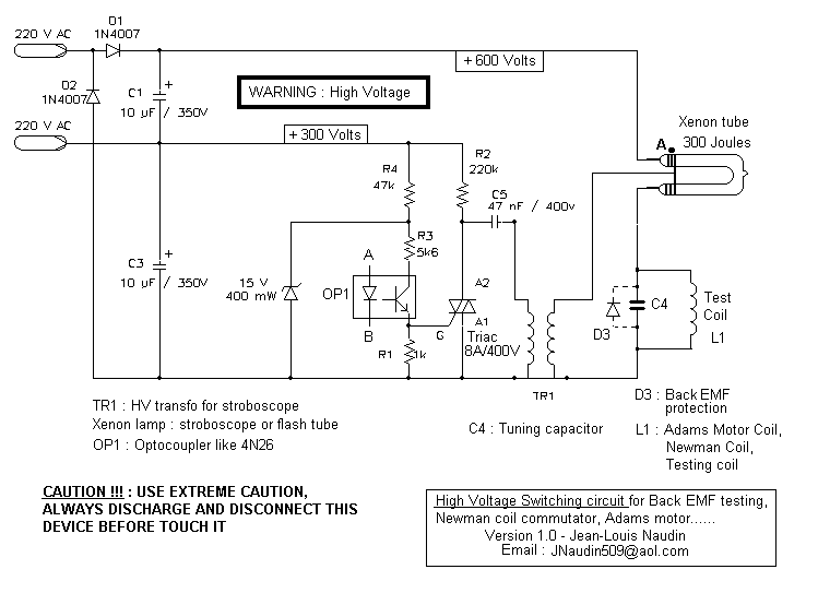
This is a High Voltage switching device for driving coils and which have big impedance when it is switched off. It can be used in Back-EMF energy recovery tests, Newman coils electronic commutator. This device is driven by an...
The "R-h sampling circuit limit order" aims to reduce the sampling resistor. A DC voltage level can be positioned between the components. The circuit includes a line amplifier that allows for magnification adjustments and is designed to protect against...
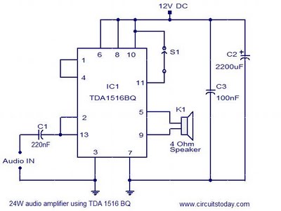
This document presents the circuit diagram of a simple 24W mono amplifier utilizing the TDA1516 integrated circuit. The TDA1516 is a Class B power amplifier housed in a 13-pin SIL package. It incorporates several beneficial features, including short circuit...
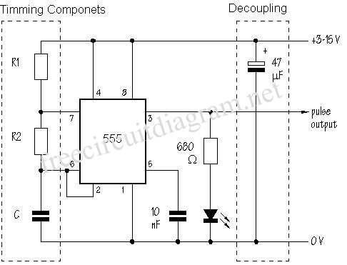
The SE555/NE555 timer was first introduced by the Signetics Corporation around 1971. Pin connections and functions are as follows: Pin 1 (Ground) - This pin serves as the ground or common pin, representing the most negative supply potential of...
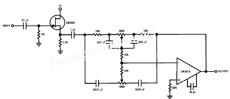
This circuit is a simple series tone control circuit utilizing the OP-Amp LM301A. The JFET 2N3684 provides high input impedance and low noise characteristics for the feedback buffer in the op-amp-based tone control. The tone control circuit described employs an...