
Ultra-high gain audio amplifier

The JFET µ-amp circuit utilizes a Junction Field Effect Transistor (JFET) to achieve its amplification characteristics. The JFET operates by controlling the current flow through a semiconductor channel via an electric field created by the gate voltage. This configuration allows for high input impedance and low output impedance, making it suitable for various applications where signal integrity is critical.
The gain of the JFET amplifier can be adjusted by varying the drain current. A lower drain current results in a higher transconductance (µ), which directly translates to increased voltage gain. However, this increase in gain comes at the cost of input dynamic range, as the circuit may become more sensitive to noise and distortion at higher gain levels.
In practical applications, the JFET µ-amp is often used in sensor signal conditioning, audio amplification, and other low-power applications where high gain is required without introducing significant power consumption. The circuit design typically includes biasing resistors to stabilize the operating point of the JFET, ensuring consistent performance across varying temperatures and supply voltages.
Overall, the JFET µ-amp circuit is a versatile and efficient solution for applications requiring high gain with minimal power usage, though careful consideration must be given to the trade-offs in input dynamic range as gain is maximized.Sometimes called the JFET µ-amp, this circuit provides a very low power, high gain amplifying function. Since µ of a JFET increases as drain current decreases, the lower drain current is, the more gain you get
Input dynamic range is sacrificed with increasing gain, however. 🔗 External reference
Related Circuits
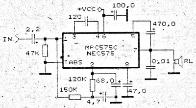
An amplifier circuit is particularly well-suited for use in confined spaces, such as within vehicles. It requires a voltage supply ranging from 9 Volts to a maximum of 17 Volts. This amplifier circuit utilizes the IC MPC575C, which is...
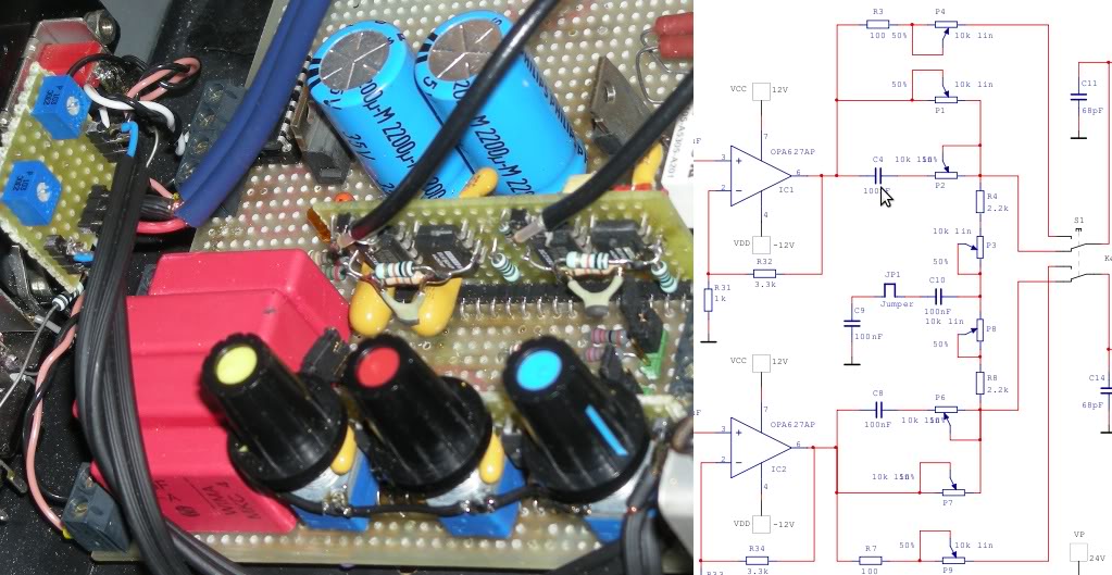
This circuit is a 6-channel audio mixer. Three channels are designated for microphone inputs, while the remaining three channels accommodate audio inputs from devices such as CD players, computers, or televisions. The circuit includes six potentiometers to control the...
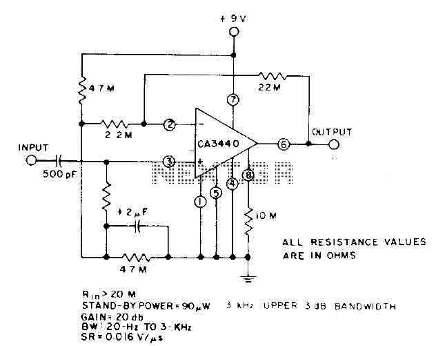
This circuit utilizes the low power leakage, high input impedance, frequency response, and capacitance characteristics of the CA3440 operational amplifier. Only one input coupling capacitor of 500 pF is required to attain a -3 dB low frequency response at...

This design circuit functions to filter out interference signals, ensuring that the signal received from a Morse code station is distinct. The circuit utilizes the earliest mode of radio communications, which employs Morse Code on a continuous wave carrier...
This is a straightforward and enjoyable project or circuit designed for those interested in experimenting with crossfeed. It is based on a Linkwitz crossfeed configuration. It is important to note the distinction between crosstalk and crossfeed, the latter also...
This circuit allows for the measurement of the actual output power of an amplifier. It can be housed in a box to function as a measurement instrument. The circuit for measuring amplifier output power typically includes a few essential components:...