
High-Performance Shortwave Converter Circuit
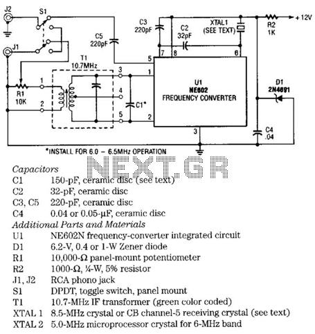
Transformer T1 rejects signals that fall outside the desired band. It should pass signals from 9 to 11 MHz while attenuating all others. The transformer T1 used in this circuit is a 10.7-MHz IF transformer salvaged from an FM radio, which can be easily sourced from parts stores and mail-order suppliers. Most 10.7-MHz IF transformers will tune across the 9.5- to 10-MHz band without modification; adjustment can be made by turning its tuning slug. To receive the 6.0- to 6.5-MHz shortwave band, a 150-pF capacitor must be added. The circuit requires the following components: Capacitors C1 (150-pF, ceramic disc), C2 (32-pF, ceramic disc), C3 and C5 (220-pF, ceramic disc), and C4 (0.04 or 0.05 µF, ceramic disc). Additional parts and materials include U1 (NE602N frequency-converter integrated circuit), D1 (6.2-V, 0.4 or 1-W Zener diode), R1 (10,000-ohm panel-mount potentiometer), R2 (1,000-ohm, 5% resistor), J1 and J2 (RCA phono jacks), S1 (DPDT toggle switch, panel mount), T1 (10.7-MHz IF transformer, green color coded), XTAL1 (8.5-MHz crystal or CB channel-5 receiving crystal), and XTAL2 (5.0-MHz microprocessor crystal for the 6-MHz band).
The NE602 chip is a versatile device that integrates both oscillator and mixer functionalities, making it suitable for various RF applications. The oscillator stage generates a stable frequency that is mixed with incoming RF signals, allowing for the extraction of desired frequency components. The output signals generated from this mixing process can be utilized for further processing or demodulation.
The design of the circuit emphasizes the importance of filtering, which is achieved through Transformer T1. This transformer is critical for ensuring that only the desired frequency range is passed to the output while unwanted frequencies are effectively attenuated. The use of a 10.7-MHz IF transformer is particularly advantageous due to its availability and compatibility with the specified frequency range.
Capacitors play a vital role in tuning and stability within the circuit. The specified values of capacitors C1 through C5 are chosen to optimize performance across different frequency bands. The addition of a 150-pF capacitor facilitates reception in the lower 6.0- to 6.5-MHz band, demonstrating the circuit's adaptability.
Overall, this circuit can serve as a foundational element for building a shortwave radio receiver, enabling users to tune into various frequencies with the appropriate choice of crystal and components. Proper assembly and tuning of the circuit will yield a functional device capable of receiving signals from specified shortwave bands. The NE602 chip, Ul, contains oscillator and mixer stages. The mixer combines the oscillator signal with the input RF signal to produce signals whose frequencies are the sum and difference of the input frequencies. For example, an 8.5-MHz oscillator and a 10-MHz incoming signal will give output signals at 18.5 MHz (10 + 8.5) and 1.5 MHz (10 - 8.5).
Recall that 1.5 MHz is 1500 kHz and an ordinary AM radio will tune to it.The choice of crystal depends on what shortwave band you want to hear. The 9.5- to 10-MHz band is less crowded and includes the time-signal station WWV. For that band, you`ll need a crystal of 8.5 to 8.9 MHz. There is no standard microprocessor crystal in that range, but you can use an amateur radio crystal, have a crystal custom-made, or use a CB crystal.
Transformer Tl rejects signals that are outside the band you are interested in. Transformer T1 should pass signals from 9 to 11 MHz and attenuate all others. The transformer, Tl, used in the circuit is a 10.7-MHz IF transformer salvaged from an FM radio. They are fairly easy to obtain new from parts stores and mail-order houses. Most 10.7-MHz IF transformers will tune across the 9.5- to 10-MHz band without modification; all you need to do is turn its tuning slug. To receive the 6.0- to 6.5-MHz shortwave band, you`ll have to add a 150-pF capacitor. * Capacitors CI 150-pF, ceramic disc (see text) C2 32-pF, ceramic disc C3, C5 220-pF, ceramic disc C4 0.04 or 0.05-, ceramic disc Additional Parts and Materials Ul NE602N frequency-converter integrated circuit, D1 6.2-V, 0.4 or 1-W Zener diode, R1 10,000-ohm panel-mount potentiometer, R2 1000-ohm, W, 5% resistor, Jl, J2 RCA phono jack, SI DPDT, toggle switch, panel mount, Tl 10.7-MHz IF transformer (green color coded), XTAL 1 8.5-MHz crystal or CB channel-5 receiving crystal (see text), XTAL 2 5.0-MHz microprocessor crystal for 6-MHz band
🔗 External reference
Related Circuits
Automatic Gain Control (AGC) is a circuit design that maintains a consistent level of amplification for sound or radio frequency signals. If the signal is too low, the AGC increases the gain to ensure the output remains at a...
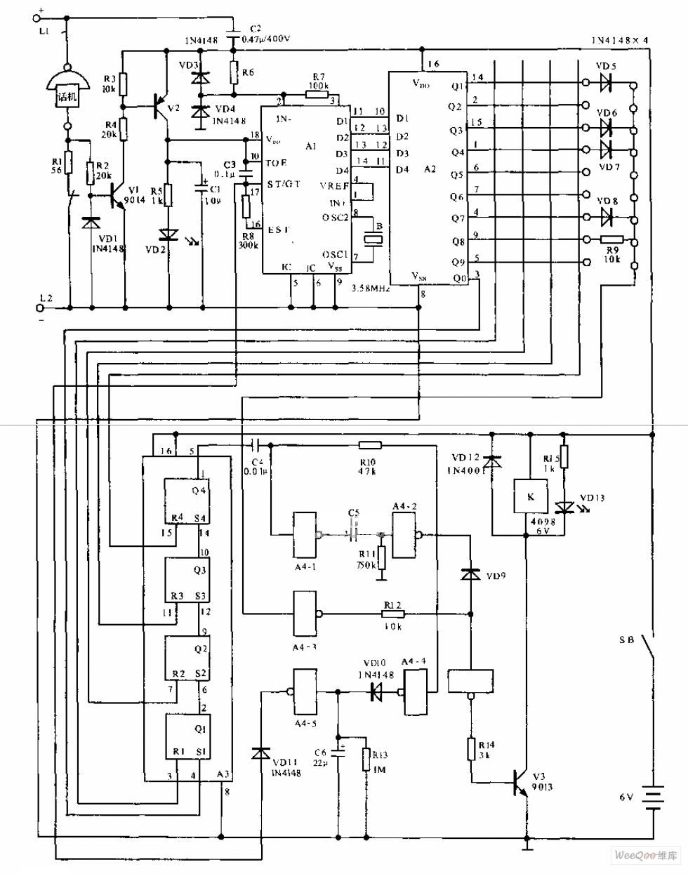
The telephone electronic coded lock circuit is designed for double audio circuits. When this coded lock is installed on a phone, dialing out requires the user to input a four-digit pre-programmed password using the phone's buttons. If the password...
Hello everyone, please examine this circuit. I constructed it recently, but it is not functioning. I have verified all connections and components, and everything appears to be in order. However, when I power it on... The circuit in question appears...
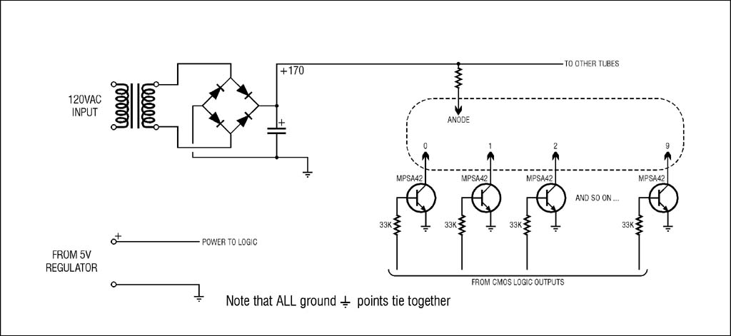
The high voltage supply will function, but for safety and to prevent accidental damage during troubleshooting with an oscilloscope, it is highly recommended to use an isolation transformer on the 120VAC input. A small 1:1 transformer rated at 30VA...
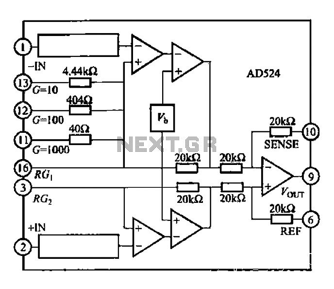
The AD524 is a low-drift instrumentation amplifier characterized by a drift voltage of 0.5 mV and a maximum drift of 25 mV at room temperature. It has low noise performance with a noise level of 0.3 mVp-p in the...

A South African company has developed a 5-kilowatt Fuel Free Generator and discovered that the longevity of the batteries is significantly affected by the process. There are various types of batteries available for testing, including different lead-acid batteries, gel...