
Building power/control interface for RGB LED strips
To design a circuit for controlling RGB LED strips through USB or Ethernet, the following components and considerations are essential:
1. **Microcontroller Selection**: A microcontroller with sufficient GPIO (General Purpose Input/Output) pins and support for USB or Ethernet communication is crucial. Options such as the ESP32 or Arduino Mega can be considered, as they offer the necessary interfaces and processing power.
2. **Power Supply**: Given the high power consumption of RGB LED strips, a robust power supply is required. A regulated DC power supply capable of delivering the total current needed for all LED strips should be selected. For example, if each RGB LED strip consumes 2A, and three strips are to be powered, a power supply rated for at least 6A at the appropriate voltage (typically 12V or 24V depending on the strip) should be used.
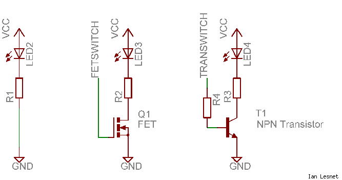
3. **LED Driver Circuit**: To control the brightness and color of the RGB strips, MOSFETs or dedicated LED driver ICs can be employed. Each color channel (Red, Green, Blue) of the LED strip can be controlled by a separate MOSFET, which acts as a switch that adjusts the power delivered to the LEDs based on the PWM (Pulse Width Modulation) signal from the microcontroller.
4. **Independently Controllable Zones**: To achieve independent control over multiple zones, a multiplexer or relay module could be integrated. This allows for the selection of which LED strip is currently being controlled based on user input or pre-defined settings.
5. **Communication Interface**: For USB control, a USB-to-serial converter can facilitate communication between the microcontroller and the controlling software on a computer. For Ethernet control, an Ethernet module (such as the W5500 or ENC28J60) can be used to enable network connectivity, allowing for remote control of the LED strips.
6. **Software Development**: The microcontroller will require firmware that handles incoming commands via USB or Ethernet, processes these commands, and adjusts the PWM signals sent to the MOSFETs accordingly. Additionally, a user interface can be developed for ease of control, whether it is a desktop application or a web-based interface.
7. **Thermal Management**: Given the high current flow, proper thermal management must be considered. Heatsinks may be necessary for the MOSFETs, and adequate ventilation should be ensured in the enclosure to prevent overheating.
This comprehensive approach will yield a functional RGB LED strip controller with the capability to manage multiple strips independently while ensuring efficient power handling and user-friendly operation.Control RGB LED strips via a USB or ethernet interface. These strips consume a lot of power and the mass produced controllers suck. I would also like independently controllable "zones" if you will, so ideally this device could power 1 or more strips. Since a picture is worth 1, 000 words I`ve attached an image of what I am trying to accomplish. Does anyone know of something like this commercially available, or how I can practically create something that will power this many LEDs At a minimum I would really like each device to power 3 strips at a time which is quite a bit of power. I`m am very new to EE, so this is all kind of overwhelming to me. 🔗 External reference
Related Circuits

Author Mazi Hosseini describes a simple, low-cost voltage-controlled current source using two operational amplifiers that provides a good range of current and maximum load. The circuit described by Mazi Hosseini utilizes two operational amplifiers (op-amps) to create a voltage-controlled current...
Build an interface board to connect scientific equipment, specifically a pair of photovoltaic tubes, to a personal computer for acquiring measurement results. The signal properties include two channels with a common ground, a one-second acquisition time, and a maximum...
This circuit is same as the above setup to drive 25 small Xmas lights. The lights operate at about 200mA and 3 volts. The supply voltage is set to 5 volts and the 4017 counter output will drop about...
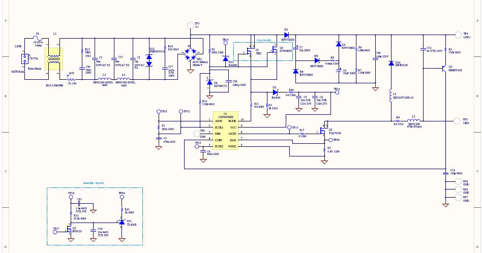
This reference design converts 90V AC to 135V AC input and drives seven or eight series-connected LEDs with an average current ranging from 300 to 600 mA. The LM3445 operates at a nominal switching frequency of 225 kHz. This...
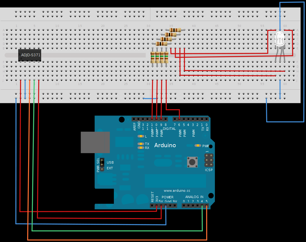
The next board presented is the ADJD-S371 Color Light Sensor Evaluation Board from SparkFun. This board emits light and analyzes the reflected color spectrum. It can be controlled via I2C, while the sleep and xclk pins were not utilized...

Before using LEDs, it is advisable to test them. An LED tester allows for testing even in low light conditions. LEDs are available in various shapes and colors, with some featuring clear, colorless packages and others having colored plastic...
Warning: include(partials/cookie-banner.php): Failed to open stream: Permission denied in /var/www/html/nextgr/view-circuit.php on line 713
Warning: include(): Failed opening 'partials/cookie-banner.php' for inclusion (include_path='.:/usr/share/php') in /var/www/html/nextgr/view-circuit.php on line 713