
40 MHz Wideband RF Amplifier
A comprehensive understanding of the wideband RF amplifier circuit reveals its essential role in modern communication systems. The AF125 transistor serves as the cornerstone of this circuit, providing the necessary amplification for high-frequency signals. Its characteristics enable effective operation within the specified frequency range, making it suitable for various applications including FM mixing and signal processing.
The BNC jack input facilitates easy connectivity, allowing for quick adjustments to receiver sensitivity. This feature is particularly beneficial in environments with significant interference, where optimizing the circuit's performance can enhance signal clarity and reliability. The resonant circuit’s design is crucial for maintaining stability and efficiency at mid and low wave frequencies, ensuring that the amplifier can handle a range of signal types without distortion.
The specified current consumption of 7 mA is indicative of the circuit's efficiency, especially considering the gain of 20 dB achieved under these conditions. The operation within a 12 V to 15 V DC supply range allows for flexibility in power sourcing, accommodating various electronic setups.
Compatibility with 75 Ohm coaxial cables is a critical design aspect, as it ensures minimal signal degradation and optimal transmission quality. The choice of cable length—short for local applications and long for broader connections—highlights the versatility of the circuit in different operational contexts.
The potential issues associated with coaxial cables, such as ground loops and signal leakage, must be considered during implementation. Proper grounding and shielding techniques can mitigate these problems, enhancing overall circuit performance.
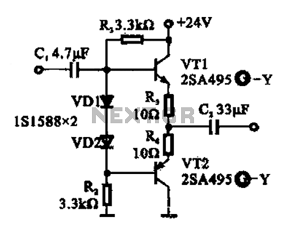
In summary, the design and functionality of wideband RF amplifiers like the one utilizing the AF125 transistor are fundamental to the advancement of communication technologies, enabling robust and high-fidelity signal transmission across a variety of applications.Wideband a transmission or communication channel or medium which consists of a wider bandwidth than one voice channel with a carrier wave of a certain modulated frequency and is capable of transmitting more information than narrowband but less than broadband AF125 a high frequency germanium PNP transistor operating at 75 MHz, with voltageof 20 V at 10 mA current, enclosed in a TO-72 package, and used for RF & IF amplifier, preamplifier mixer, FM mixer, and oscillator up to 900 MHz The input of the circuit comes from the BNC jack where the sensitivity of the receiver can be adjusted to increase accordingly. This can be achieved in the presence of interference between the circuit and the aerial source of the RF amplifier.
The resonant circuit used in the amplifier circuit is made to be suitable for mid waves and for the low waves which oscillates up to 40 MHz. The circuit is consuming a total of 7 mA of current while the gain is in the measurement of 20 dB. All these values are due to the presence of a 12 V up to 15 V DC supply. The input and the output of the circuit are designed to be compatible with coaxial cables with complex resistance of 75 Ohms.
Short coaxial cables are being used for ham radio setups, home video equipment, and in measurement electronics while long coaxial cables are used for connecting television, radio networks or telephone companies. There are some problems that have been encountered in using coaxial cables such as ground loops, common current and radiation, induction, signal leakage, and transformer effect.
The idea behind the construction of wideband RF amplifiers may be found in RF measuring equipment, communication receivers like GPS receivers, and other related devices. They are designed to operate in conjunction with its series of waveform generators that will provide a solution for wideband, high-voltage applications.
🔗 External reference
Related Circuits
High-quality, very simple unit; no need for a preamplifier. Amplifier parts: P1 = 22K, R1 = 1K, R2 = 4.7K, R3 = 100R, R4 = 4.7K, R5 = 82K, R6 = 10R-1/2W, R7 = 22R, R8... This circuit describes a...
A buffer amplifier is utilized as a transistor emitter follower buffer amplifier for applications that necessitate a high input impedance. The circuit employs a complementary push-pull configuration. The signal input is connected to the base of transistor VT1, which...
A unit that is often very useful for isolating two stages in sound circuits. This circuit incorporates an amplification unit with a gain of X1. It employs only local negative feedback rather than total negative feedback, resulting in very...
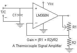
Continuing with the thermocouple interface concept, the next step is to amplify the TC's millivolt signal into a more readable analog voltage, on the order of 0 to 5VDC. This simple circuit fits the bill. The LM358N is a...
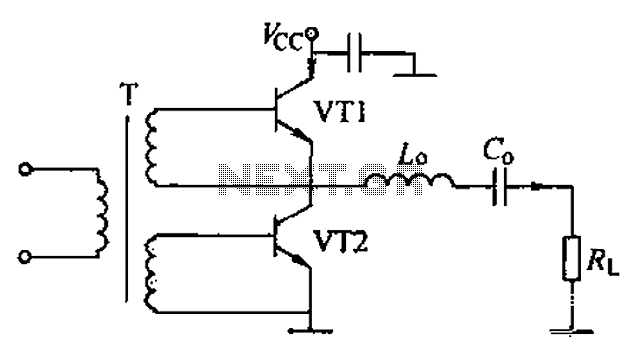
A complementary voltage switching Class D amplifier circuit is presented. Transistors VT1 and VT2 are 3DA12 types, while another transistor, VT3, is of the 3DK41C type. The collector is connected to a constant DC voltage of 12V. The input...
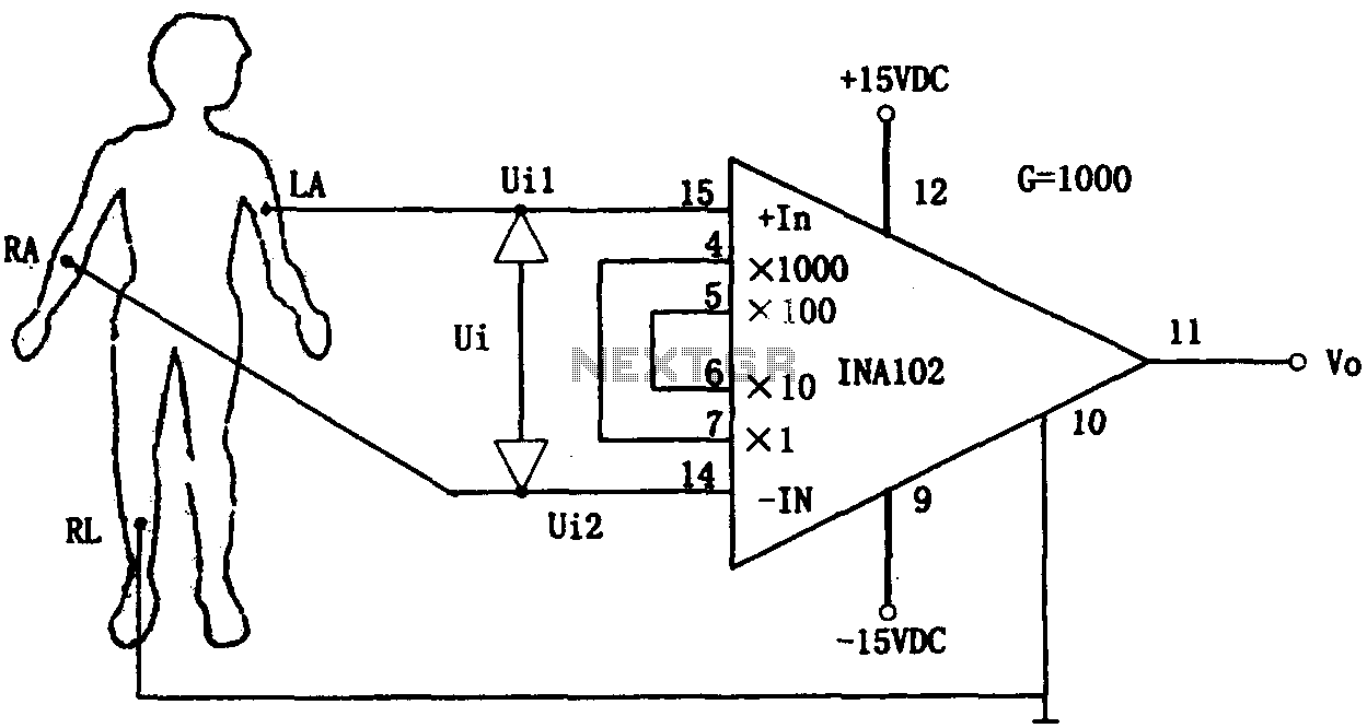
This document outlines a preamplifier circuit designed for measuring human biological signals, such as ECG and EEG. These biological signals are typically weak and require high amplification circuits. The circuit utilizes a low-power integrated operational amplifier, INA102. The INA102...