
Railway Grade Crossing Circuit
The Grade Crossing circuit provides prototypical o peration of the signals at level railway crossings and can supply up to 100 milliamps for LED flashers, small incandescent lights or other circuits such as crossing gates or sound units. The circuitboard has been designed to be easy to build and install. Widely available and inexpensive components are used in its construction. None of the parts are static sensitive. An upgraded version of the 2004 circuit is at this link - 2008 - Automatic Railway Grade Crossing Circuit.
The new circuit designed to prototypically control crossing gates. The following diagrams show how the circuit is connected for a crossing with 1 track. A diagram of the circuit board showing the terminal block positions is used. The next diagram shows how the phototransistor sensors are placed along the track and the actions that occur as each is covered by the train. The sensors that start the flashers can be placed any distance from crossing desired. The signals will remain ON until approximately two seconds after the last car has passed completely through the crossing, uncovering both of the "STOP" sensors.
As the train leaves the protected section of track, the "DISABLE" sensors prevent the flashers from being turned ON again by deactivating the "START" sensors. The circuit is ready for the next train in either direction approximately five seconds after the "DISABLE" sensors are uncovered.
If the departing train is still covering a "START" sensor after this time the flashers will turn on again. Manual controls can start or stop the flashers as desired. The START push button could be replaced by a toggle switch in order to keep the flashers activated during switching operations.
Normal room lighting is used to detect the trains. If night operation is needed the circuit can be controlled by other circuits or by providing infrared light for the sensors. The Crossing Circuit requires a regulated 12 volt power supply. The current draw is about 3 milliamps when the flashers are OFF and about 35 milliamps when they are ON.
Crossing gates and bells can be controlled buy using the MultiTrack terminal as an output to control these devices. The MultiTrack terminal is also used to connect the circuitboards together for crossings with two or more tracks.
WARNING - If the polarity of the power supply for this circuit is reversed or the circuit is connected AC or DCC source, the circuit will be damaged. The maximum supply voltage is 15 Volts DC. The following picture is the printed circuit board for the Automatic Grade Crossing circuit. The board is two inches by four inches and has been commercially made and pre-tinned. (An assembled example of the board is also shown. ) NOTE: - The above prices include 6 visible/infrared sensitive, 3mm diameter phototransistors. The phototransisitor have 5 inch - Red and Black leads soldered to them and are tested before shipment.
When installing the components on the circuit board start with parts with the lowest height and work up to the tallest parts. For example starting with the jumper wires then diodes then resistors, IC`s, transistors, capacitors and terminal blocks.
The following diagrams shows how two and three circuitboards are connected for multiple track crossing with full automatic protection for each track. Any number of tracks can be protected using circuitboards for each track at the crossing. The diagrams above show one circuit board for each protected track at a crossing. It is possible to use one circuit board to protect multiple tracks but fully automatic control is not possible when this is done.
Two tracks at a crossing can be protected by a single circuit by placing additional sensors in series with the sensors of the first track. This is a cost saving measure. Because only one circuitboard is used, fully automatic operation is not possible as with the two circuitboard - two track crossing but if only one train uses the crossing at a time, the system will give prototypical operation.
Because only one circuit is used, fully automatic operation is not possible as in the full two track crossing but if only one train uses the crossing at a time, the system will give prototypical operation. The printed circuit board for the 556 Timer Stall-Motor Switch Machine Drivers circuit could be used to make Crossing Gate motor drivers.
See the "Additional Circuits" section of the page. The circuit in the following link will allow the crossing flasher LEDs to be connected using only two wires instead of three as in the circuits above. This could make wiring of small scale signals easier. Unconfirmed - The LEDs in the Walters # 933-2914 crossing signals are wired in a common anode circuit but the Black wire is the positive and the Red wires are the negative.
The 22 ohm resistors distribute the current evenly though the LEDs. The 1K ohm resistors limit the current flow through the LEDs and can be changed if the brightness of the LEDs needs to be adjusted. This circuit when used with a 555 timer will cause light emitting diodes to turn on and off more slowly.
This will make the LEDs appear similar to incandescent lamps. This circuit can be used to drive higher current light bulbs that are found in older or large scale signals. The adapter can be connected directly to the Automatic Grade Crossing circuit or through optoisolators if a separate power supply is to be used for the bulbs.
If there is electrical noise that causes the crossing circuit to trigger falsely, small capacitors can be added to the input terminals. This will make the crossing circuit slightly slower to activate but will not affect the operation of the circuit.
This is an updated version an LM555 timer based - Grade Crossing Bell Ringer - circuit that was built for the London Model Railroad Group. The circuit drives a warning bell that is shown on the page. CIRCUIT MODIFICATIONS - The value of R1 may be lowered and the value C1 increased to give a more powerful coil current for a louder ring.
Some experimentation may be needed to determine the best values for a particular situation. BELL MODIFICATIONS - The circuit-breaking contacts of the bell`s solenoid are not used and have been bypassed by connecting the blue wire directly to the coil. The armature has been bent so that less throw is needed for it to strike the gong. Home Depot carries a bell in their electical section that is similar to the one shown on this page. The model number is 172C and the stock number is 106 419 🔗 External reference
Related Circuits
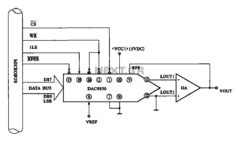
Figure 8 illustrates a typical digital-to-analog (D/A) conversion circuit that utilizes the DAC0830/DAC0832 chip. The microprocessor outputs an 8-bit digital signal, which is converted into an analog signal. The D/A conversion circuit depicted employs the DAC0830/DAC0832, which is a dual...
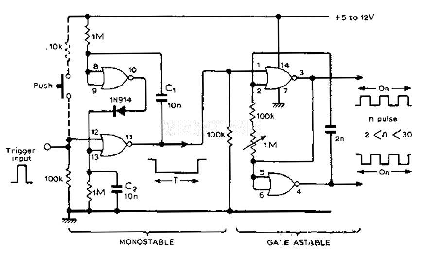
Each trigger input can produce a fixed number of pulses, with the range being from 2 to 30. The specific number is determined by the frequency-controlled settings of 1 megohm. A monostable gated unsteady power supply circuit can be...
The working principle of this inexpensive and simple-to-build metal detector circuit involves mixing two equal frequencies, which results in a low-frequency interference. The metal detector circuit operates on the principle of heterodyning, where two frequencies are combined to produce a...
Which switch mode power supply (SMPS) topology should one start with? Although the schematic of a full-bridge looks a bit complicated compared to push-pull and half-bridge designs, sticking straight to a full-bridge topology or its smaller version, the half-bridge,...
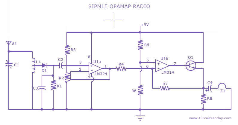
A low-cost, simple radio circuit schematic using an operational amplifier. This radio circuit diagram consists of a sensitive audio amplifier that receives strong signals. The presented radio circuit schematic utilizes an operational amplifier (op-amp) to create a cost-effective and straightforward...
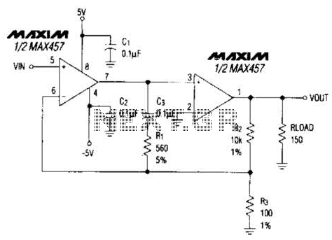
A composite amplifier can be constructed that offers high gain, wide bandwidth, and good DC accuracy by cascading the sections of a dual video amplifier and incorporating two suitable phase compensation components. The operational amplifier drives a 150-ohm load...
Warning: include(partials/cookie-banner.php): Failed to open stream: Permission denied in /var/www/html/nextgr/view-circuit.php on line 713
Warning: include(): Failed opening 'partials/cookie-banner.php' for inclusion (include_path='.:/usr/share/php') in /var/www/html/nextgr/view-circuit.php on line 713