
High Power Solid State Amplifier
The design of a solid-state linear amplifier using Motorola's MRF150 power FETs presents an innovative approach to achieving high efficiency and performance in the HF range. The push-pull configuration allows for parallel operation of multiple FETs, which significantly enhances output power while minimizing losses associated with traditional power combiners. The high input impedance characteristic of the FETs allows for greater flexibility in circuit design, enabling more straightforward integration into existing systems.
The amplifier's power supply must be designed to deliver a stable 50 VDC at sufficient current to support the operation of the FETs under load. A secondary lower voltage supply for biasing will also be critical to ensure optimal performance across the desired frequency bands. Adequate heat dissipation is paramount; therefore, the selection of heat sinks and thermal management solutions should be considered early in the design process to prevent thermal runaway and ensure reliability.
The enclosure for the amplifier should be constructed from materials that provide adequate shielding and thermal conduction while maintaining a compact footprint. Careful attention to layout will help minimize parasitic inductance and capacitance, which can adversely affect performance, especially at higher frequencies.
To address harmonic suppression, a low-pass filter should be implemented at the output stage to mitigate unwanted emissions and comply with regulatory standards. The design of this filter will need to account for the amplifier's operational bandwidth and the specific characteristics of the output stage.
Overall, the proposed solid-state linear amplifier design leverages modern FET technology to create a robust and efficient solution for amateur radio applications, with a focus on ease of use, safety, and performance across multiple HF bands.Building a solid-state linear amplifier. I have an old Heathkit SB 221 that after a major overhaul and redesign is now working great on 80, 40, 20, and 15; but not 17, 12 and 10. With this in mind I got on the internet at the motel we were staying in and started searching for ideas.
One design kept popping up that seemed to be the most popular and offered what seemed to be the best approach. Back in the early 1980`s Motorola developed a line of Power FET`S. for amplifiers and other end uses. Helge Granberg, one of their circuit engineers, wrote a number of application papers for the use of these power FET`S. Over the years his designs have become widely used and to some degree the standard for commercially built solid-state amplifiers.
His application EB104 seemed to me to be the best and most practical design for what I wanted for the upper bands in the HF range. Specification highlights that briefly describes the idea behind the design and an exert from his paper follows.
This unique push-pull circuit produces a power output of four devices without the added loss and cost of power splitters and combiners. Motorola MRF150 RF power FET makes it possible to parallel two or more devices at relatively high power levels.
This technique is considered impractical for bipolar transistors due to their low input impedance. In a common source amplifier configuration, a power FET has approximately five to ten times higher input impedance than a comparable bipolar transistor in a common emitter circuit. The DC supply voltage and power level determines the output impedance in both cases. The limit to the number of FETs that can be paralleled is dictated by physical, rather than electrical restrictions, where the mutual inductance between the drains is the most critical aspect, limiting the upper frequency range of operation.
The magnitude of these losses is relative to the impedance levels involved, and becomes more serious at lower supply voltages and higher power levels. Since the minimum mounting distance of the transistors is limited by the package size, the only real improvement would be a multiple die package.
For higher frequency circuits, these mutual inductances could be used as a part of the matching network, but it would seriously limit the bandwidth of the amplifier. This technique is popular with many VHF bipolar designs. Several motivating factors kept my interest moving forward, namely: (1) the idea of being able to work with safe voltages (50 VDC) was appealing compared to the dangerous levels present in my Heathkit SB221, (2) the ability to switch bands and not worry about retuning or changing settings was very likable, and; (3) the fun and challenge of building your own topped off the list.
After reading everything I could gather up the challenges became clear. First, the project would need a high current DC power source at 50 volts; and probably a secondary lower voltage for the bias. Next on the list of issues was the need to dissipate a lot of heat that emanates from the four power FETs.
- about 500 watts or so. In addition I wanted the amplifier to be somewhat compact and presentable to the rest of my shack , so I needed to think of a suitable enclosure. Finally, the one negative aspect of the devices is their harmonic suppression characteristics, and some form of low pass filtering would be needed to deal with the odd order dissipation.
The powers supply considerations centered on the need for 50 volts and 20 p 🔗 External reference
Related Circuits
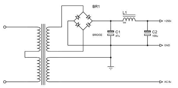
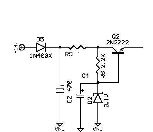
Power supply for a simple high-quality tube amplifier class A power supply. This power supply circuit is part of a series of simple high-quality tube amplifier class "A" designs. It may also be applicable to other devices. Detailed explanation:...
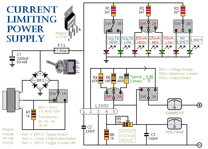
SW3 is the on/off switch. It also lets you choose between the output with the current limit and the one without. SW2 provides a selection of three different limits. You can increase or decrease this number if you wish....
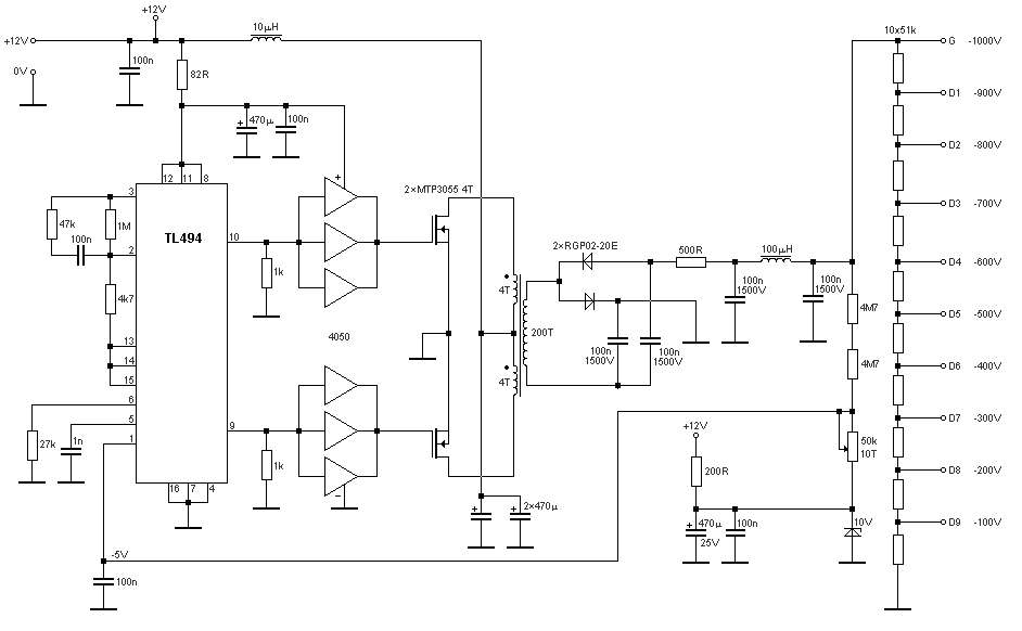
The schematic diagram originates from a circuit designed for a stable power supply ranging from -100V to -1000V. For further details, refer to the page that explains the circuit diagram associated with this power supply. This stable power supply...
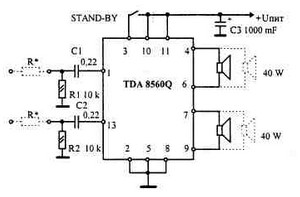
This car audio amplifier provides an output of 40 watts when connected to a 2-ohm speaker. The amplifier circuit delivers a power output of 40 watts per channel at a 2-ohm load and 22 watts at a 4-ohm load....
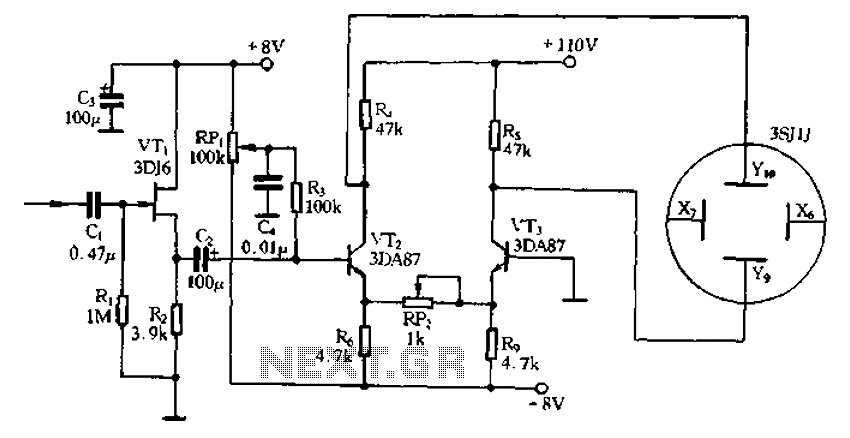
Application of the differential amplifier circuit in a simple small oscilloscope. The differential amplifier circuit is a crucial component in the design of a simple small oscilloscope. This circuit is designed to amplify the difference between two input voltage signals...
Introduction The SP6648 integrated synchronous boost regulator is a compact circuit that provides ultra-high efficiency drive current for an LED flashlight using a Luxeon I light source. The circuit is configured to deliver a constant output current of 350mA...