
High quality Stereo FM transmitter using BA1404
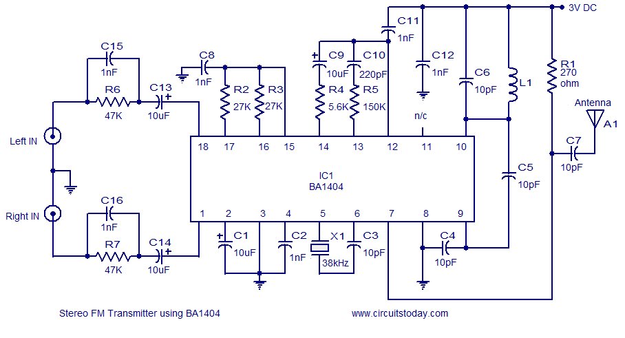
The FM transmitter circuit utilizing the BA1404 integrated circuit (IC) is engineered for simplicity and efficiency, making it an excellent choice for various audio transmission applications. The BA1404 IC is specifically designed for FM transmission, featuring low power consumption and high-quality audio output, which is ideal for battery-operated devices.
The circuit typically operates on a 3 V power supply, which can be provided by a standard battery, ensuring portability and ease of use. The primary components of the circuit include the BA1404 IC, a few passive components such as resistors and capacitors, and an antenna for signal transmission.
The BA1404 IC facilitates modulation of the audio signal, allowing it to be transmitted over FM frequencies. The circuit configuration includes an audio input stage where the audio signal is fed into the IC. The modulation process occurs within the IC, converting the audio signal into an FM signal suitable for transmission.
An essential aspect of the design is the antenna, which plays a critical role in radiating the modulated signal. The choice of antenna type and its length can significantly affect the transmission range and quality.
In summary, this FM transmitter circuit is characterized by its straightforward design, reliance on the BA1404 IC for signal modulation, and operation from a low-voltage power source, making it a versatile choice for hobbyists and applications requiring wireless audio transmission.A simple and high quality FM transmitter circuit designed based on the BA1404 IC .This FM transmitter circuit can be operated from a 3 V battery.. 🔗 External reference
Related Circuits

The range of this FM transmitter is approximately 100 meters when powered by a 9V DC supply. The circuit consists of three stages. The first stage is a microphone preamplifier constructed using a BC548 transistor. The second stage is...
The objective of this lab is to create a decimal counter that counts from 0 to 99 using the 80X51 microcontroller. A C program must be written for this purpose, which will then be compiled using the C51 compiler...
The personal radar system utilizes the PIC microcontroller PIC18F452 as a hobby project. The attached circuit diagram of the radar may appear simple; however, careful analysis of the PIC18F452 radar circuit is necessary to prevent damage. This personal radar...

The circuit consists of a language and sound FM transmitter. It is mounted on a 25mm x 35mm PCB, designed to be placed on a table. When activated by pressing the micro switch SA, the circuit transmits an FM...
In this circuit, a 74HC14 hex Schmitt trigger inverter functions as a square wave oscillator to drive a small signal transistor configured as a class C amplifier. The oscillator frequency can be set to a fixed value using a...
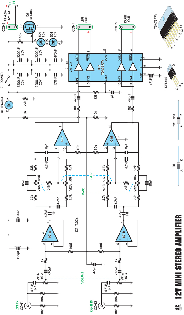
Amplifiers that operate on 12V DC typically do not produce significant power and are often not high fidelity. However, this compact stereo amplifier meets the requirements for power and low distortion. With a supply voltage of 14.4V, it can...