
Medium-Power FM Transmitter
The FM transmitter circuit operates effectively within a range of approximately 100 meters, making it suitable for short-range communication applications. The design incorporates three distinct stages, each serving a specific function to ensure optimal signal transmission.
The first stage, a microphone preamplifier, is vital for capturing audio signals. The choice of the BC548 transistor facilitates amplification of low-level audio signals, preparing them for further processing. This stage is crucial for ensuring that the audio input is adequately boosted before being sent to the next stage.
In the second stage, the VHF oscillator, the circuit generates a radio frequency signal. The use of a BC548 transistor in this role demonstrates its versatility, as it can perform effectively in RF applications despite its common association with low-frequency circuits. This oscillator is responsible for modulating the audio signal onto a carrier wave, which is essential for FM transmission.
The third stage features a class-A tuned amplifier designed to enhance the strength of the RF signal generated by the oscillator. This amplification is critical for extending the transmission range, allowing the signal to travel further distances. The additional RF amplifier significantly contributes to the overall performance of the transmitter.
Coils L1 and L2 are integral components of the circuit, providing the necessary inductance for tuning and signal amplification. The construction of these coils using 20 SWG enameled copper wire ensures efficient signal handling. Coil L1, with its four turns, is designed for initial signal processing, while Coil L2, with six turns, further refines the signal for transmission.
The antenna plays a pivotal role in the effective broadcasting of the FM signal. A 75 cm long wire is specified to maximize the range, allowing the transmitter to reach its full potential. The performance of the transmitter can be significantly enhanced when paired with a sensitive receiver, which is capable of picking up weak signals.
To facilitate fine-tuning of the transmitter, VC1 is employed as a frequency-adjusting trimpot, allowing for minor adjustments to the operational frequency. VC2 is another variable capacitor that should be calibrated to achieve the best transmission range, ensuring that the transmitter operates efficiently within its designated frequency band.
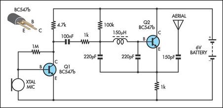
Powering the entire circuit is a 9V PP3 battery, providing a stable and reliable source of energy for the transmitter's operation. This compact power supply makes the circuit suitable for portable applications, such as creating a walkie-talkie system when combined with a compatible FM receiver kit. Overall, this FM transmitter circuit design offers a practical solution for short-range wireless communication.The range of this FM transmitter is around 100 meters at 9V DC supply. The circuit comprises three stages. The first stage is a microphone preamplifier built around BC548 transistor. The next stage is a VHF oscillator wired around another BC548. (BC series transistors are generally used in low-frequency stages. But these also work fine in RF stage s as oscillator. ) The third stage is a class-A tuned amplifier that boosts signals from the oscillator. Use of the additional RF amplifier increases the range of the transmitter. Coil L1 comprises four turns of 20SWG enameled copper wire wound to 1. 5cm length of a 4mm dia. air core. Coil L2 comprises six turns of 20SWG enameled copper wire wound on a 4mm dia. air core. Use a 75cm long wire as the antenna. For the maximum range, use a sensitive receiver. VC1 is a frequency-adjusting trimpot. VC2 should be adjusted for the maximum range. The transmitter unit is powered by a 9V PP3 battery. It can be combined with a readily available FM receiver kit to make a walkie-talkie set. 🔗 External reference
Related Circuits
Long-distance infrared transmitter circuit diagram. This simple circuit offers a considerable range by utilizing three infrared transmitting LEDs (IR1 through IR3) in series to enhance the radiated power. To further improve directivity and power density, the IR LEDs can...
This schematic for an experimental data transmitter utilizes optical fibers and a laser diode. The transmission frequency of the free-running oscillator is approximately 3 kHz. Resistor R5 may need to be adjusted to match the specifications of the laser...
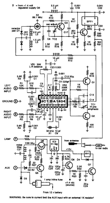
A BA1404 integrated circuit (IC) is utilized to generate a complete FM multiplex (MPX) signal. The chip incorporates all necessary circuitry. Components CI, R3, R4, and C4 are responsible for providing pre-emphasis. The transmitter operates on a single AA...

A low power FM pirate radio. The output power is approximately +35 dBm (3.16 watts) over a 50-ohm load and operates on a +24-volt power supply. The project consists of a Hartley oscillator (modulated VCO) and three stages (Class...
This AM transmitter is notably simple to construct due to its design, which features a non-tapped inductor with a single winding. The inductor is not custom-wound, as it can be sourced from readily available RF chokes, such as the...

The transmitting signal can be picked up by any FM radio receiver. Most often used in cars. The problem with most FM transmitters is that they have very weak signals and short transmitting ranges. Some units are so poor...