
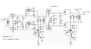
Micro Power AM Broadcast Transmitter
The circuit employs the 74HC14 hex Schmitt trigger inverter due to its ability to provide a clean square wave output, which is essential for driving the subsequent transistor stage effectively. The Schmitt trigger's hysteresis characteristics enhance the stability of the oscillator, allowing it to maintain consistent frequency output even in the presence of noise.
In the VFO configuration, the oscillator frequency is determined by the RC time constant of the capacitor and resistor network. The choice of a 100pF capacitor allows for a range of operating frequencies, which can be adjusted by varying the resistance in the circuit. This flexibility makes the circuit suitable for applications requiring frequency modulation or tuning.
The output from the 74HC14 is connected to the base of a small signal transistor, which operates in class C mode. In this configuration, the transistor conducts for less than half of the input signal cycle, resulting in high efficiency and the ability to amplify high-frequency signals. The class C amplifier is particularly effective in RF applications where signal amplification is required without significant power loss.
The overall design of this circuit is compact and efficient, making it ideal for various electronic applications, including signal generation and amplification in communication devices. Proper selection of components, particularly the resistor and capacitor values, is crucial for achieving the desired frequency response and stability in the oscillator output.In this circuit, a 74HC14 hex Schmitt trigger inverter is used as a square wave oscillator to drive a small signal transistor in a class C amplifier configuration. The oscillator frequency can be either fixed by a crystal or made adjustable (VFO) with a capacitor/resistor combination.
A 100pF capacitor is used in place of the crystal for VFO operation 🔗 External reference
Related Circuits
The objective is to investigate low RPM issues and gather expert opinions before proceeding with the disassembly of wire looms for tracing purposes. To address low RPM problems in an electronic system, it is essential to conduct a thorough analysis...
Long-range FM transmitter. The power output of most of these circuits is very low because no power amplifier stages were incorporated. The transmitter circuit described here has an. The long-range FM transmitter operates by modulating a carrier frequency with an...

A 5V Switch Mode Power Supply utilizing the LM2674 power supply. Refer to the corresponding page for an explanation of the related circuit diagram. The 5V Switch Mode Power Supply (SMPS) designed with the LM2674 integrates a step-down (buck) converter...
This is an RF Power Amplifier designed for low-cost QRP applications. The circuit operates over a broadband frequency range of 1.8 to 30 MHz, eliminating the need for tuning. The only adjustment required is to set the quiescent current...
The exciter board is based on an Arduino WSPR exciter. Plans are underway to create a more advanced stand-alone board using inexpensive Chinese DDS modules available from eBay. Currently, a DDS60 by AmQRP is being utilized. The output from...
This small circuit transmitter processes audio signals from a sound table or microphone, as well as video signals from a camera, DVD, or video cassette. It has a composite video output, allowing direct transmission from a computer over a...
Warning: include(partials/cookie-banner.php): Failed to open stream: Permission denied in /var/www/html/nextgr/view-circuit.php on line 713
Warning: include(): Failed opening 'partials/cookie-banner.php' for inclusion (include_path='.:/usr/share/php') in /var/www/html/nextgr/view-circuit.php on line 713