
High Voltage Switching for Energy Recovery

The high voltage switching device described operates as a critical component in applications involving inductive loads, such as coils with high impedance characteristics when deactivated. The architecture of this device typically integrates a high-voltage transistor or a thyristor, which is responsible for switching the power to the coil. The use of an opto-coupler for driving this switch ensures electrical isolation between the control circuit and the high-voltage side, enhancing safety and reliability.
In operation, the device can be utilized in Back-EMF energy recovery tests, which are essential for improving the efficiency of inductive loads by capturing the energy released when the coil is de-energized. The integration with Newman coils and electronic commutators allows for precise control of the switching sequence, which is crucial for applications requiring synchronisation with mechanical components, such as plastic shutters.
The opto-switch connection facilitates a synchronized operation, allowing the device to be triggered at specific intervals, thereby optimizing the performance of the commutator system. It is imperative to incorporate adequate protective measures, such as fuses and circuit breakers, to safeguard against potential overcurrent conditions. Additionally, a thorough understanding of the voltage ratings and the discharge procedures for any capacitors within the circuit is essential to ensure user safety, particularly when working with high-voltage systems.
Proper layout and component selection are critical in minimizing the risks associated with high voltage. This includes using components rated for the maximum expected voltage and ensuring that the PCB design accommodates adequate spacing for high-voltage traces to prevent arcing or short circuits.This is a High Voltage switching device for driving coils and which have big impedance when it is switched off. It can be use in Back-EMF energy recovery tests, Newman coils electronic commutator.....This device is drived by an opto-coupler and can be easily connected with an opto-switch for synchronisation phase (with plastic shutters) with a Newman commutator device for instance.....
BE CAREFULL, USE EXTREME CAUTION !!!, this device use High voltage, disconnect and discharge capacitor before touch it. 🔗 External reference
Related Circuits
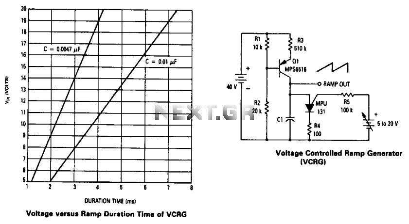
The current source created by Q1 in combination with capacitor C1 determines the duration of the ramp. As the positive DC voltage at the gate varies, the peak point firing voltage of the Programmable Unidirectional Thyristor (PUT) is altered,...
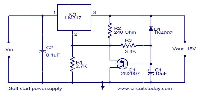
This post presents an interesting topic about switching power supply circuit diagrams for those who wish to learn more. A switching power supply is a type of power supply that uses a switching regulator to convert electrical power efficiently. Unlike...
If a negative supply is required for an operational amplifier or if a negative bias voltage is needed while operating from a single supply voltage, such as in battery applications. To generate a negative supply voltage from a single positive...
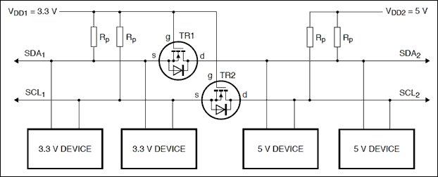
Construct a logic level shifter using discrete components such as transistors and resistors, or opt for a single-component solution with an integrated circuit (IC). Many ICs do not accept input voltages as low as 1.4 V; however, the Fairchild...
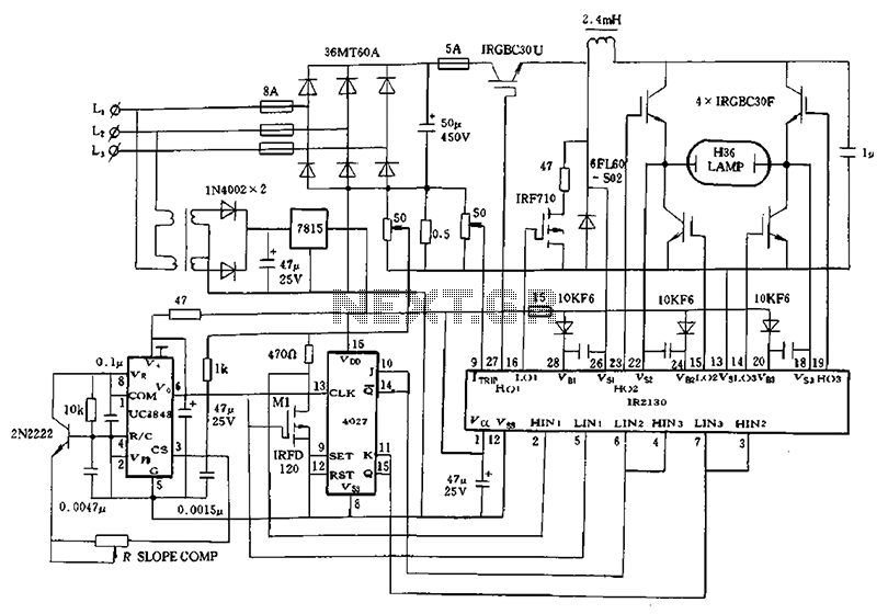
Application of a kilowatt high-pressure mercury lamp ballast system; the schematic in Figure 12.44 illustrates the IR213D used for a high-pressure mercury lamp ballast system. The IR2130 is utilized not only to drive a single-phase full-bridge inverter with four...
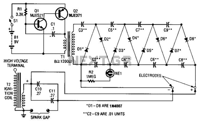
This circuit employs a transistor oscillator and a voltage multiplier to charge capacitors CIO and CI1 to a high voltage. When the spark gap breaks down, T2 generates a high-voltage pulse through the discharge of capacitors CIO and CI1...