
high side current measurements
The INA138 and INA168 ICs are designed for precision current sensing applications, utilizing a shunt resistor to measure current indirectly. The shunt resistor, characterized by its low resistance value, is strategically placed in series with the load whose current is to be measured. When current flows through the shunt, a corresponding voltage drop occurs, which is proportional to the current according to Ohm's law (V = IR). The IC then amplifies this voltage drop to provide a usable output signal.
For accurate measurements, the selection of the shunt resistor value is crucial; it should be low enough to minimize power loss while still producing a measurable voltage drop. The gain settings determined by the load resistor (RL) allow for flexibility in scaling the output signal to suit various applications. This adaptability is particularly useful in systems where different current ranges must be monitored.
The internal operation of the IC involves a feedback mechanism that ensures the differential voltage across the shunt is maintained at a specific level, enabling precise current measurement. The use of a transistor (T1) for adjusting the voltage at the positive input enhances the IC's ability to maintain accuracy across a wide range of input voltages. The design of the INA138 and INA168 allows for high common-mode voltage rejection, ensuring that variations in supply voltage do not adversely affect the measurement.
In practical applications, the output can be interfaced with analog-to-digital converters (ADCs) for digital processing or displayed on analog meters. The flexibility in supply voltage and input range makes these ICs suitable for battery management systems, power monitoring applications, and other scenarios where accurate current measurement is essential. Proper implementation of these ICs will yield reliable and precise current measurements, contributing to the overall efficiency and performance of electronic systems.It`s always a bit difficult to measure the current in the positive lead of a power supply, such as a battery charger. Fortunately, special ICs have been developed for this purpose in the last few years, such as the Burr-Brown INA138 and INA168.
These ICs have special internal circuitry that allows their inputs to be connected directly to either end of a shunt resistor in the lead where the current is to be measured. The shunt is simply a low-value resistor, across which a voltage drop is measured whenever a current ¬‚ows. This voltage is converted into an output current Io by the IC. This current can be used directly, or it can be converted into a voltage by means of a load resistor RL.
In the latter case, the ¬‚oating` measurement voltage across the shunt is converted into a voltage with respect to earth, which is easy to use. The value of RL determines the gain. A value of 5 k gives 1G—, 10 k gives 2G—, 15 k gives 3G— and so on. It all works as follows. Just like any opamp, this IC tries to maintain the same potential on its internal plus and minus inputs.
The minus input is connected to the left-hand end of the shunt resistor via a 5-k resistor. When a current flows through the shunt, this voltage is thus lower than the voltage on the plus side. However, the voltage on the plus input can be reduced by allowing a small supplementary current to flow through T1.
The IC thus allows T1 to conduct just enough to achieve the necessary lower voltage on the plus input. The current that is needed for this is equal to Vshunt / 5 k. This transistor current leaves the IC via the output to which RL is connected. If the value of RL is 5 k, the resulting voltage is exactly the same as Vshunt. The IC is available in two versions. The INA138 can handle voltages between 2. 7 and 36 V, while the INA168 can work up to 60 V. The supply voltage on pin 5 may lie anywhere between these limits, regardless of the voltage on the inputs.
This means that even with a supply voltage of only 5 V, you can make measurements with up to 60 V on the inputs! However, in most cases it is simplest to connect pin 5 directly to the voltage on pin 3. Bear in mind that the value of the supply voltage determines the maximum value of the output voltage.
Also, don`t forget the internal base-emitter junction voltage of T1 (0. 7 V), and the voltage drop across the shunt also has to be subtracted. 🔗 External reference
Related Circuits
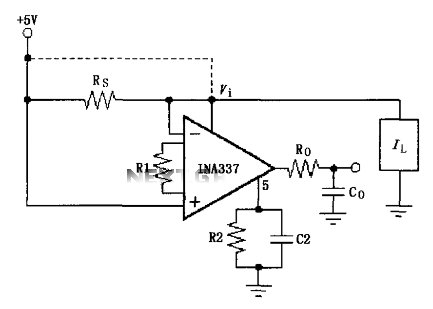
The INA337 circuit, as illustrated, is part of a load current measuring shunt circuit. It generates a voltage drop across the sampling resistor Rs, which is connected in series between the power source and the load. The load current...
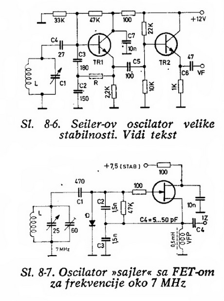
Will an LC-based oscillator be able to demonstrate performance comparable to crystals under such conditions (possibly in unusual configurations like LC-opamp) so that any energy loss at each stage is recovered, resulting in a narrower bandwidth? Examine some amateur...
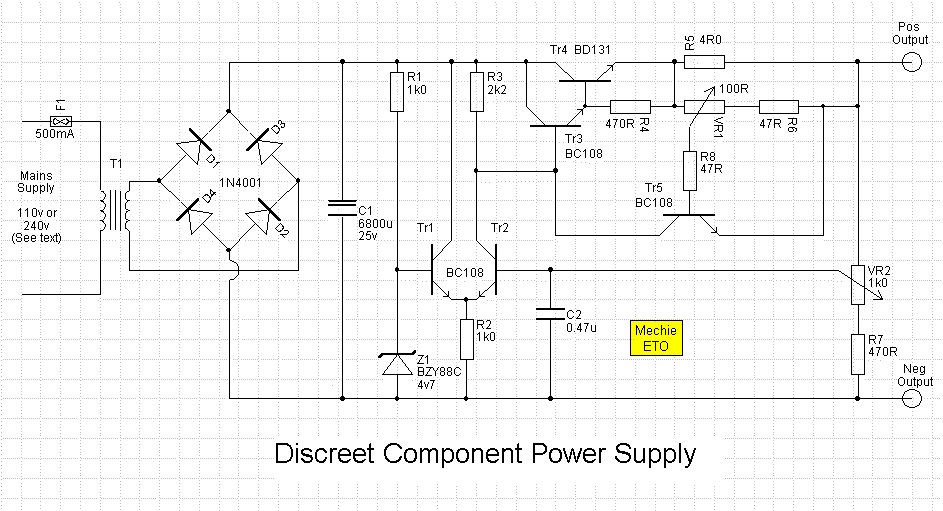
An error amplifier is constructed using transistors Tr1 and Tr2, configured as a differential amplifier, commonly referred to as a long-tailed pair, with the collector leads being a notable feature. One input of this differential amplifier is sourced from...
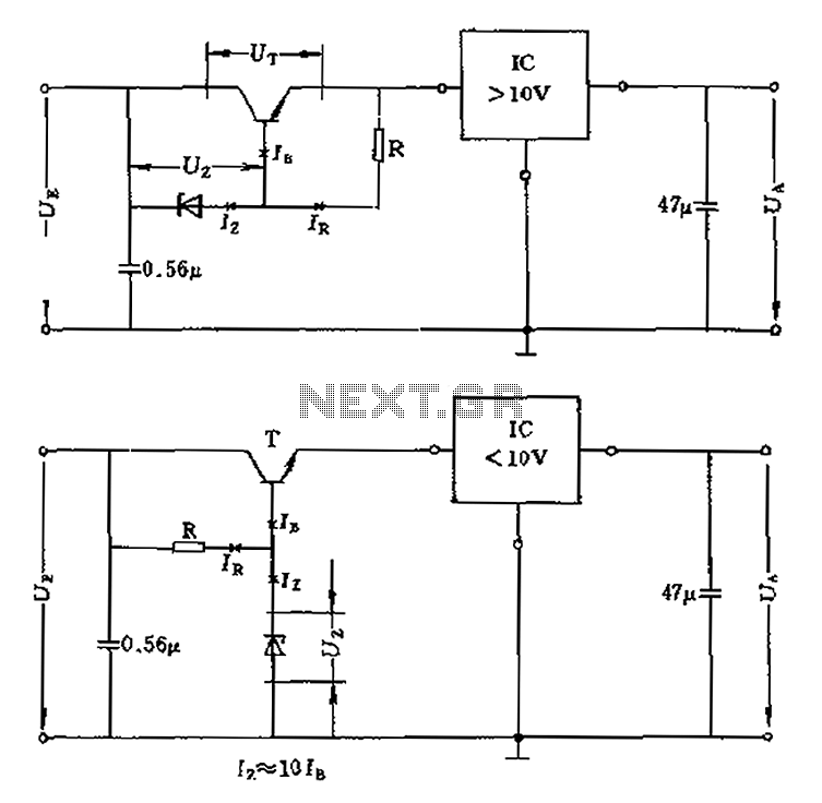
The voltage equation Ue = Ut + Ur + Ua indicates that the transistor voltage Ut will determine the maximum output voltage Ua. Additionally, Ur must be 2V. The voltage regulator's voltage value depends on the selection of Uz....
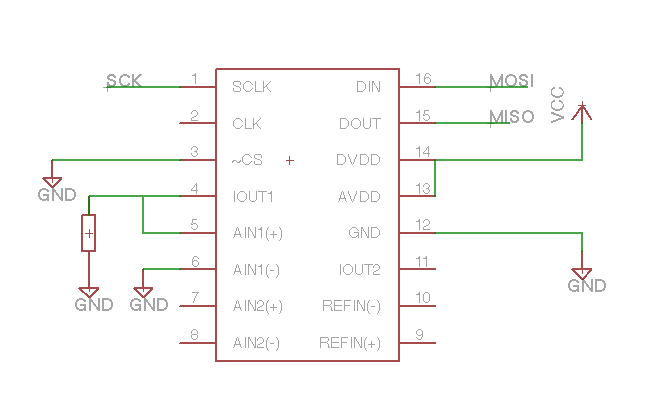
The serial interface is functioning correctly, as it reads the ID register accurately. However, the on-chip current sources do not appear to operate as expected. A 470-ohm resistor has been connected to IOUT1, and the IO register has been...
High-voltage power supply circuit for fluorescent light power supply. Refer to that page for an explanation of the related circuit diagram. The high-voltage power supply circuit designed for fluorescent lights typically consists of several key components that work together to...
Warning: include(partials/cookie-banner.php): Failed to open stream: Permission denied in /var/www/html/nextgr/view-circuit.php on line 713
Warning: include(): Failed opening 'partials/cookie-banner.php' for inclusion (include_path='.:/usr/share/php') in /var/www/html/nextgr/view-circuit.php on line 713