
High speed data switch circuit
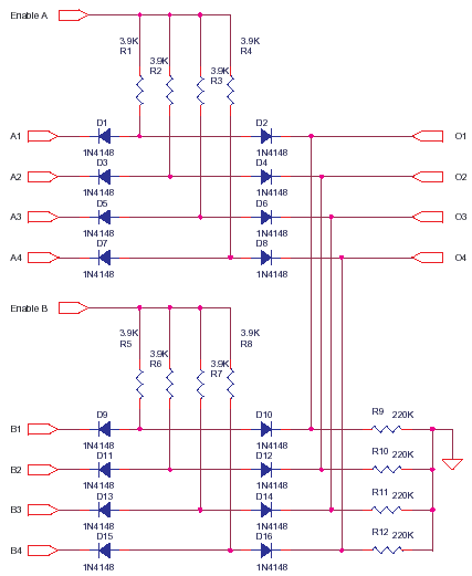
This printer sharing circuit utilizes a simple architecture to facilitate the connection of multiple printers to a single output. The core functionality hinges on the Enable A and Enable B lines, which control the routing of data from the respective input sets (A1-A4 and B1-B4) to the output lines (O1-O4). The high output impedance necessitates the incorporation of buffers or drivers to ensure signal integrity, particularly over longer distances where capacitance and resistance in the cabling could degrade performance.
The circuit design allows for flexibility in the configuration of inputs and outputs. By employing logic gates or multiplexers, the system can be expanded to support additional input sets, making it adaptable for various applications. The fast switching capability of the 1N4148 diode ensures that data can be transmitted quickly, minimizing delay, which is critical in printer data communication.
In practical applications, care must be taken to avoid excessive loading on the output lines. The recommendation to use drivers is essential when interfacing with long printer cables, as the inherent capacitance and resistance of the cables can create signal degradation. Therefore, the implementation of suitable driver circuits will enhance the performance and reliability of the printer sharing device, ensuring that it can operate effectively in diverse environments.
Overall, this circuit serves as a foundational model for printer sharing solutions, demonstrating key principles of electronic design, including impedance matching, signal routing, and the importance of component selection in achieving desired performance characteristics.This circuit is a small representation of a very low cost printer sharer i made very long ago. This is as much i can remember of the basic ideas behind the product. I used to pot the product in epoxy with a black dye and sold a few, they sort of served the purpose. Output impedance of this circuit is high, sink is 220K source is 3.9K+ so use some buffers or drivers at Output. when Enable A is at float-high impedance or low the output O1-O4 is not influenced by A1-A4 inputs. If Enable A is made logic high or 5V then A1-A4 is available at O1-O4. By turning Enable A or Enable B high, you can route the data A1-A4 or B1-B4 to the output O1-O4, you can also mix data and you can expand to any number of input sets or data width.
1N4148 is fast, 4nS, that makes this data switch quite fast. This circuit cannot drive long printer cables without drivers. They will load the output. 🔗 External reference
Related Circuits
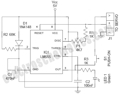
A servo is an error-sensing feedback control mechanism used to correct the performance of a system. A servo motor is a DC motor equipped with a servo mechanism. A servo motor is an electromechanical device that utilizes a closed-loop control...
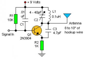
Experimenting with the size of the coil and the number of turns can influence the frequency and signal output of the oscillator. The signal can be received using a standard FM radio receiver. The input signal should be coupled...

This is a BTL (bridged tied load) mono amplifier with a DC volume control circuit. This circuit utilizes the TDA7052A/AT, which is suitable for monitors, TVs, and battery-operated portable radios and recorders. Unlike conventional DC volume circuits, the TDA7052A/AT...
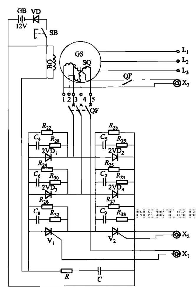
The setup is connected to separate stator windings of a harmonic generator, which leads to a thyristor rectifier supply for the third harmonic voltage, positioned after the motor field. The output voltage varies with changes in the winding harmonics...
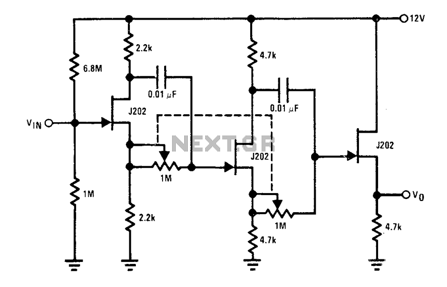
Each J202 JFET stage provides up to 180 degrees of phase shift controlled by a 1 megohm potentiometer. The potentiometer allows for complete control of the groups. JFETs are ideal for the designated circuit because they do not load...

R4 prevents the output voltage from drifting toward one of the supply rails of the operational amplifier. It is understood that R4 should have a high resistance, although the reason for this is unclear. The schematic appears to be...